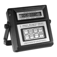
ADM-880C 07/20/0936
6.5.1 CHEMICAL EXHAUST HOODS - VELGRID
The VelGrid provides the average of 16 measurement points at 3.5 inch centers, and represents a 14" x 14" area for each
reading. When using the VelGrid for chemical exhaust hood readings, the sash opening must be set at a minimum opening
of 14 inches in width for horizontal sliding sash, or 14 inches in height for vertically adjustable sash. If the opening is less
than 14 inches in width or length, the AirFoil probe should be used.
The VelGrid must be carefully positioned so that the perimeter orifices of the VelGrid are at least 1.75 inches in from the
edge of the opening. The leading (side the air strikes first) surface of the VelGrid should be evenly aligned and parallel with
the plane of the sash. Correct positioning of the VelGrid is easier if equal length, stiff wire "feelers" are taped to the leading
surface of the VelGrid. Coat hanger wire taped in place with plastic electrical tape works well for this purpose.
6.5.2 LAMINAR FLOW WORKSTATION - VELGRID
The VelGrid can be used to measure average face velocities at the work zone or plane of a laminar work station using much
the same method as described for chemical exhaust hoods. It is important to position the leading edge of the VelGrid at
90 degrees to the direction of air flow when measuring work zone velocities. The VelGrid may also be positioned so the
1.5 inch standoffs are placed directly against the perforated supply panel face. The velocity average obtained in this manner
can be used to calculate the volumetric air flow rate as described in Section 6.5.3 AIR FLOW CALCULATION.
6.5.3 AIR FLOW CALCULATION FROM VELGRID VELOCITY
Accurate volumetric air flow calculation using the average face velocity requires careful measurement of the active gross
face area of the filter, grille, coil, or opening. Be sure to deduct the area of all obstructions to air passage through the device
to be tested, such as: support bands; T-bars, including the perimeter glue line; and repaired areas of HEPA filters.
Even with careful measurement of the active area, the meter and the sensing probe will be affected by different design
configurations of the outlet, inlet, filter, coil or exhaust hood. It is best to establish a procedure and confirm the air flow by
pitot tube duct traverse or some other reliable flow measurement means for a given type of air movement device.
IMPORTANT: See Section 6.1 VELOCITY CORRECTION FACTORS.
The measurement of exhaust hood intake velocity requires careful placement of the VelGrid to align the leading edge of
the grid directly in line with the plane of the sash opening. Maintain the 1.5" perimeter margin as illustrated. The total intake
area and air flow of an exhaust hood includes all areas of air entry, including the space behind and around the sash; under
the threshold; and through service openings. It is accepted practice to assume that the velocity through these additional
areas is the same as that of the sash opening area. (See the following section regarding hot wire anemometer reading
correction for true air velocity).
6.6 VELOCITY: LOCAL DENSITY VERSUS STANDARD DENSITY (MASS FLOW)
The AirData Multimeter measures true air velocity past the sensor at a given time, when used in the local density mode.
This is in contrast to thermal anemometers or "hot wire" instruments which measure mass flow (mass flux/unit time). Mass
flow represents the number of molecules of air flowing past a given point during a given time. Mass flow only represents
true velocity when measured at standard sea level conditions of 29.921 in Hg and 70
/ F (.075 lbs/cu ft). Hot wire, mass flow,
"velocity" readings at density conditions other than standard must be corrected for local air density conditions if these results
are to represent true velocity.
Air velocity readings taken with the ADM-880C in the standard density mode are comparable to readings taken with a hot
wire anemometer. If local density corrected velocity readings taken with the AirData Multimeter are to be compared with
hot wire anemometer readings, the actual air velocity should be measured in the local density mode with the AirData
Multimeter, and the hot wire readings must be corrected for local air density conditions.
The precise method for calculating density corrected air velocity measurements taken with a hot wire anemometer requires
the use of the following equation:
Where: P
b
= local barometric pressure (in Hg)
/ F = temperature of air stream
 Loading...