Shure LX4 Diversity Receiver
Service Procedures1525D1008 (BK)
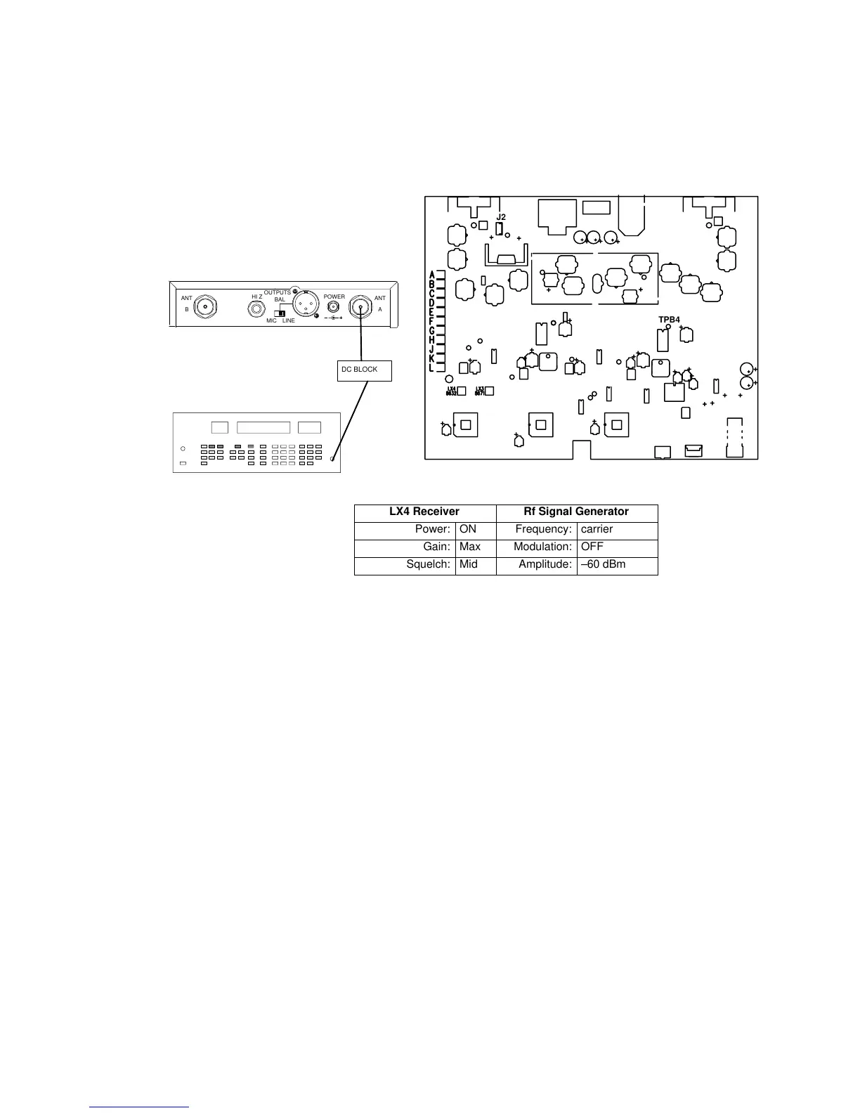
Alignment
The following steps are for channel A; channel B, is in parentheses.
For example, TPA7 (TPB7) means to use TPA7 for channel A and
TPB7 for channel B.
RF SIGNAL GENERATOR
NOTE: DC VOLTAGES ARE PRESENT AT MOST RF TEST POINTS. USE A DC
BLOCK ON THE RF SIGNAL GENERATOR TO PROTECT TEST EQUIPMENT.
TP9
TPA4
12.5 – 18.9 VDC
ANTANT
OUTPUTS
HI Z
BAL
MIC LINE
POWER
AB
TPB4
J2
DC BLOCK
LX4 Receiver Rf Signal Generator
Power: ON Frequency: carrier
Gain: Max Modulation: OFF
Squelch: Mid Amplitude: –60 dBm
Figure 3. Alignment Test Setup
1. Solder a 33 kΩ resistor between TPA4 (TPB4) and ground for rf
adjustments. Do the same for channel B with TPB4.
2. Set the rf signal generator frequency to the same as the LX4,
with no modulation, and its amplitude at –60 dBm.
3. Connect the power supply (PS40) to 120 Vac power and to the
receiver’s dc input connector (J2). The green power on LED of
the LX4 should now be illuminated. If not, there is a circuit mal-
function.
4. Connect the rf signal generator to the 50 Ω antenna input for
channel A or channel B, as appropriate.
5. Verify that 10.0 ± 0.35 Vdc is present at TP9 (U7, pin 3), using a
digital multimeter (DMM).
Preset the adjustable circuit components as follows:
6. Set volume (R32) control fully clockwise.
7. Set squelch (R66) control to midrange.
8. Turn the LX4 power OFF.
 Loading...


