Shure LX4 Diversity Receiver
16
Service Procedures
25D1008 (BK)
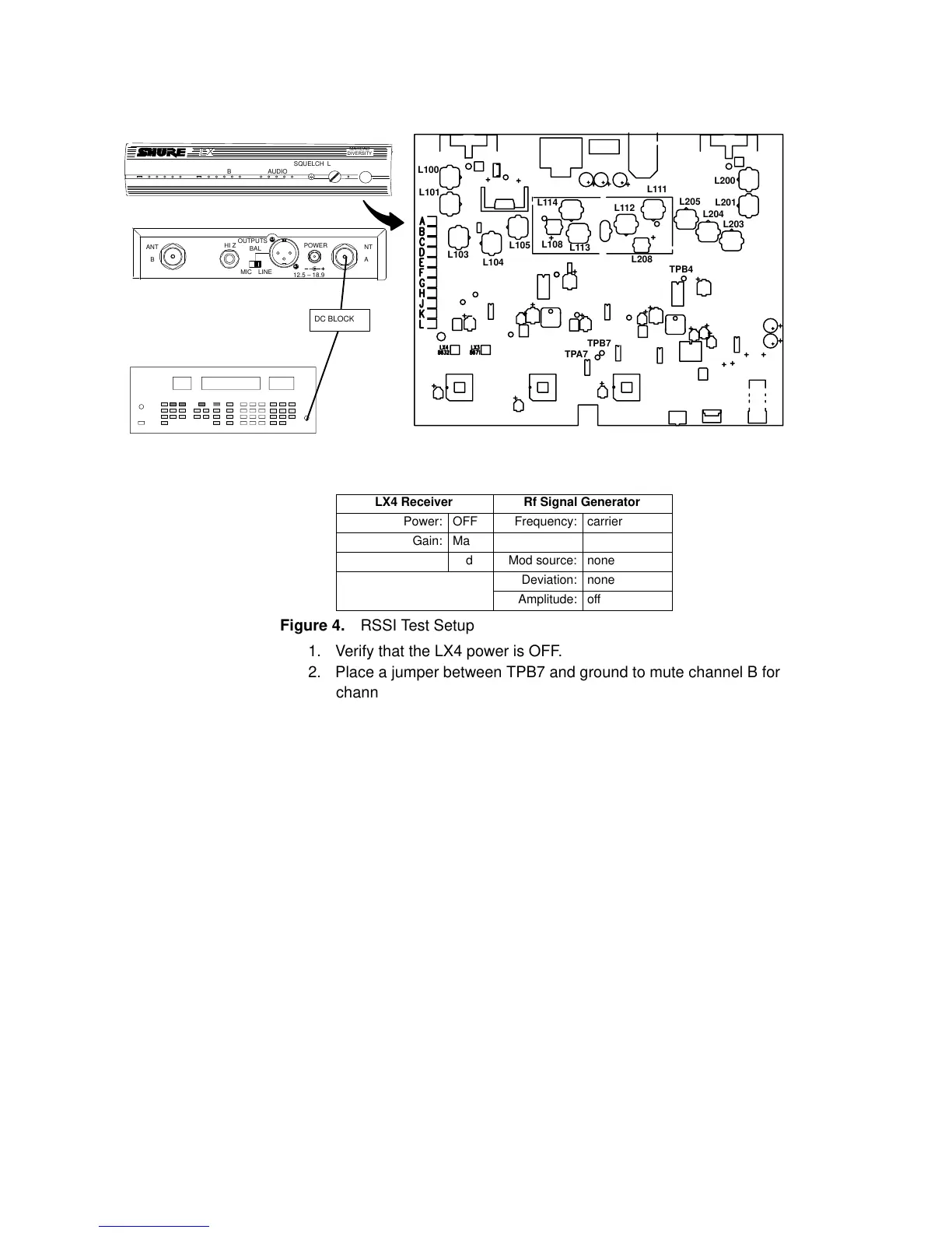
Received Signal Strength Indicator (RSSI) Adjustment
RF SIGNAL GENERATOR
NOTE: DC VOLTAGES ARE PRESENT AT MOST
RF TEST POINTS. USE A DC BLOCK ON THE
RF SIGNAL GENERATOR TO PROTECT
TEST EQUIPMENT.
TPA4
12.5 – 18.9 VDC
POWER
RF A RF B
AUDIO
SQUELCH LEVEL
ANTANT
OUTPUTS
HI Z
BAL
MIC LINE
POWER
AB
MARCAD
DIVERSITY
TPB4
TPA7
TPB7
L100
L101
L103
L104
L105
L114
L108
L113
L112
L111
L208
L205
L204
L203
L200
L201
DC BLOCK
LX4 Receiver Rf Signal Generator
Power: OFF Frequency: carrier
Gain: Max Modulation: off
Squelch: Mid Mod source: none
Deviation: none
Amplitude: off
Figure 4. RSSI Test Setup
1. Verify that the LX4 power is OFF.
2. Place a jumper between TPB7 and ground to mute channel B for
channel A alignment. (Place a jumper between TPA7 and
ground to mute channel A for channel B alignment.)
3. Turn the LX4 power ON.
4. Measure dc voltage at TPA4 (TPB4).
5. Adjust rf signal generator rf output so that approximately
2.0 Vdc is measured at TPA4 (TPB4).
6. If this is unattainable even with 0 dBm generator output, adjust
L108 (L208) until the voltage is above 2.0 Vdc. If adjusting L108
(L208) does not produce more that 2.0 Vdc at TPA4, return it to
the preset position and adjust L113 and L114 (L111, L112).
7. Adjust coils L100, L101, L103, L104, L105, L108, L113, and L114
(L200, L201, L203, L204, L205, L208, L111, and L112) for maxi-
mum voltage at TPA4 (TPB4). Use a hex-tuning wrench for all
adjustments except L108 (L208), which requires a non-metallic
screwdriver.
8. Reduce the rf signal generator output level as required to keep
signal voltage under 3.0 Vdc.
9. Final adjustments should be performed with an rf signal
generator output level of approximately –85 dBm.
Repeat this test for channel B.
Note: Inductance increases as the core is turned clockwise into
the coil. The maximum inductance position is approximately two
 Loading...


