English
1
SHURE T SERIES USER GUIDE
This user guide provides detailed instructions for your T series wireless system. To get your system up and running in
minutes, see the T Series Quick Set Up Guide.
Your new T Series system is designed to give you both the freedom of a wireless system and world-famous Shure sound
quality. This manual covers both Standard and Diversity versions of each of the T Series systems: The Guitarist, The
Vocal Artist, The Presenter , The Headset, and The Bodypack Wireless systems.
Wireless
System
Components
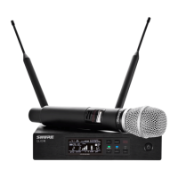
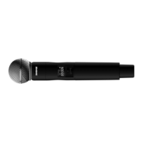
The Vocal Artist
Hand-held system
for singers.
The Guitarist
Bodypack system for
electric and bass gui-
tarists. Can also be
used with other elec-
tric instruments
The Headset
Bodypack system for
applications requiring
hands-free operation,
such as aerobics or
percussion
The Presenter
Bodypack system for
public speaking, the-
ater, or business pre-
sentations.
The Bodypack
Wireless
Configurable systems
for use with various
microphones.
Transmitter T2 Handheld
Transmitter
T1G Bodypack
Transmitter (T11 Europe)
T1 Bodypack
Transmitter (T11 Europe)
Microphone
SM58
or PG58
–– WH20 Headset
Microphone
WL93 omnidirectional
lavalier, WL185 cardioid
or WL184 super cardioid
––
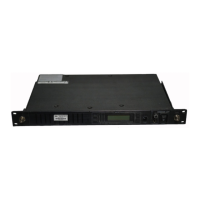
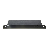
Receiver T3 single antenna or T4N Diversity
Power Supply PS20 (105–125 VAC, 60 Hz) or PS20E (230 VAC, 50 Hz) or PS20UK (230 VAC, 50 Hz)
Battery 9–volt alkaline (Duracell MN 1604)
Supplied Carrying and storage case; Receiver feet; Hook and loop fastening strips; gain adjustment screwdriver
Accessories
microphone stand
adapter
1/4” to 1/4” cables (2);
(Europe: 1/4” to Mini Con-
nector and 1/4” to 1/4”)
RECEIVER FEATURES
1
2
3
4
5
.
.
.
.
.
.
.
.
.
.
T3
T4N
7
9
SHURE BOTHERS INC.
EVANSTON
IL
60202
USA
12–18 VDC
DC INPUT
UNBALANCED
HIGH
Z
BALANCED
SQUELC H
MIN MAX
ÁÁÁÁÁÁÁ
ÁÁÁÁÁÁÁ
ÁÁÁÁÁÁÁ
ÁÁÁÁÁÁÁ
8
3
1
2
4
5
6
6
8
7
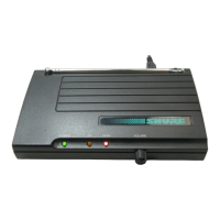
FIGURE 1. T3 AND T4N RECEIVER FEATURES
1. Power On Indicator: Glows green when the receiver is
powered on.
2. RF Signal Indicator: T3: Glows yellow when RF (radio fre-
quency) signals are received. T4N: One of two indicator
lights glows when RF is received by antenna A or B.
3. Transmitter Audio Peak Indicator: Flashes red when the
audio signal received approaches overload clipping level.
4. Volume Control: Adjusts the output volume of the receiver.
Does not affect Transmitter Audio Peak indicator.
5. Telescoping Antenna(s): Receives signals from the trans-
mitter.
6. Audio Output: Provides mic level signal for connection to
amplifiers or mixing consoles. T3: 1/4 inch phone jack. T4N:
1/4 inch phone jack and male XLR connector.
7. Squelch Control: This control is factory pre-set and nor-
mally requires no adjustment. See “Wireless System Ad-
justments.”
8. Power Input: Accepts power from supplied AC adapter.
9. Power Cable Retainer: T4N only. Secures the AC adapter
cable to the receiver.
 Loading...