Shure U4D Dual Diversity UHF Receiver
30
25D1062 (AG)
Service Procedures
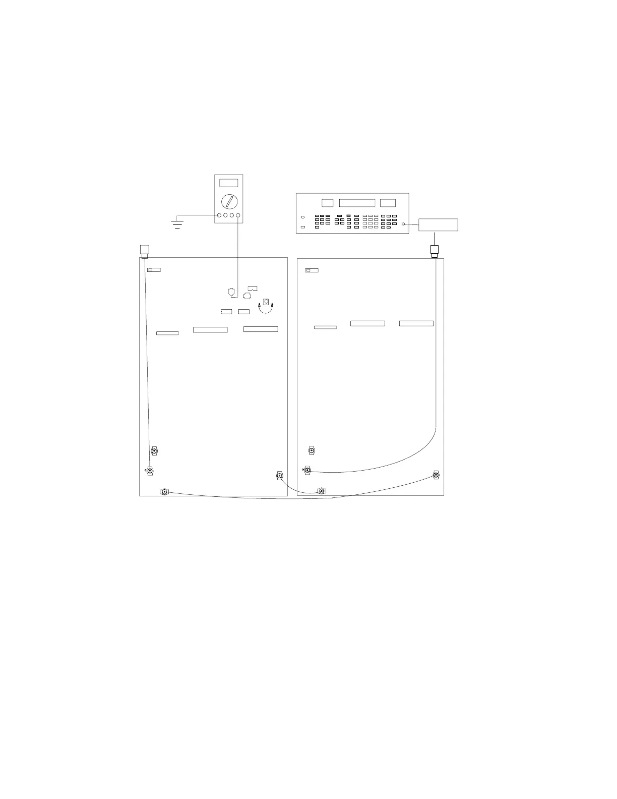
Noise Setup (Channel B)
The Noise Setup procedure aligns each Channel so that for a given
signal-to-noise ratio, the respective dc levels match.
P202
P203
P202
S201
ANTENNA A IN
ANTENNA B IN
DC VOLTMETER
P202
P202
P203
S201
C242
U202
C239
U203
U211
R265
RF SIGNAL GENERATOR
DC BLOCK
NOTE: DC VOLTAGES ARE PRESENT
AT MOST RF TEST POINTS. USE A DC
BLOCK ON THE RF SIGNAL GENERATOR
TO PROTECT TEST EQUIPMENT.
(OFF) (OFF)
J302
Figure 14. Channel B, Noise Setup Connections
1. Set the modulating frequency from the audio analyzer to 60 kHz
and, if necessary, readjust the amplitude so HI EXT and LO EXT
lights turn off.
2. Verify that the rf signal generator output power is –61 dBm.
3. Place the (+) terminal of a dc voltmeter on the (+) side of C242
and connect the (–) terminal to ground.
4. For 34A8507F or earlier PCB versions, adjust R389 (not shown
above) until the voltmeter reads 8.00 ± 0.03 Vdc. For 34A8507G
or later PCB versions and PCB 34A8703, adjust R265 to 4.00 ±
0.03 Vdc.