Shure U4D Dual Diversity UHF Receiver
31 25D1062 (AG)Service Procedures
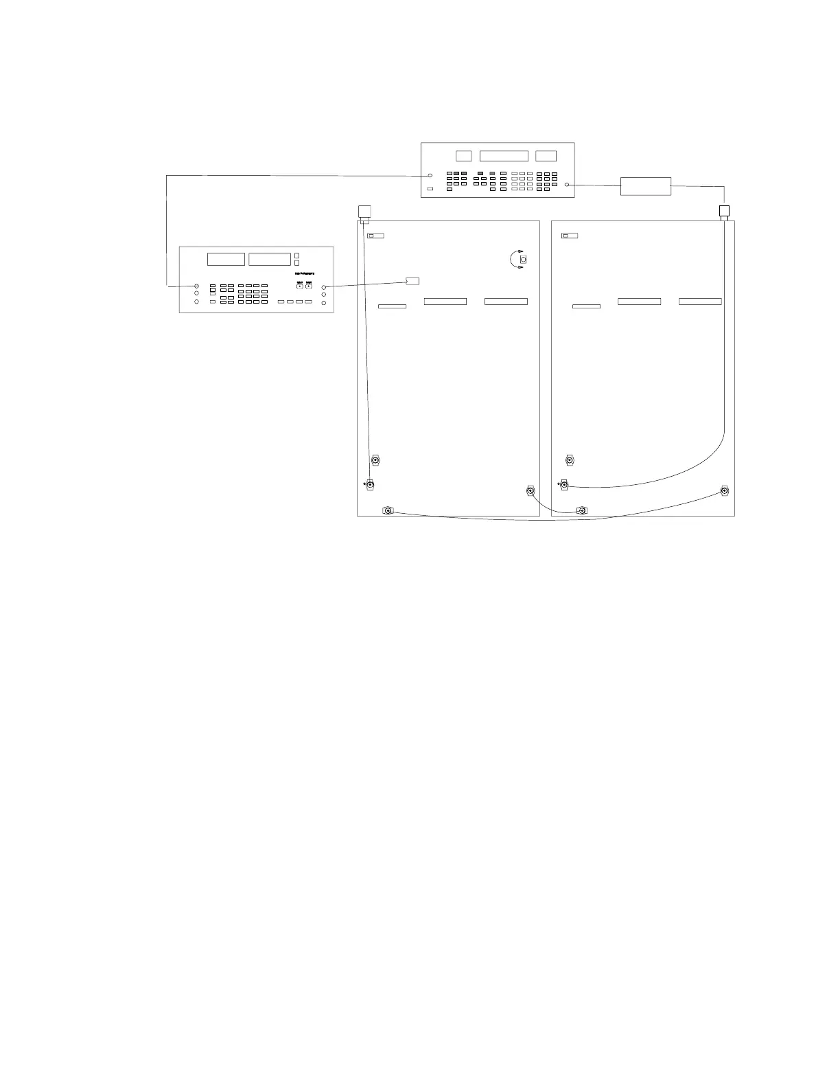
Audio Level Setup, Channel B
U207
R250
P202
P202
P203
S201
ANTENNA A IN
P202
P202
P203
S201
ANTENNA B IN
RF SIGNAL GENERATOR
PIN 7
DC BLOCK
NOTE: DC VOLTAGES ARE PRESENT
AT MOST RF TEST POINTS. USE A DC
BLOCK ON THE RF SIGNAL GENERATOR
TO PROTECT TEST EQUIPMENT.
(OFF)
(OFF)
J302
AUDIO ANALYZER
Figure 15. Channel B Audio Level Setup Connections
For the following test, make sure the tone key switch (S201) is OFF.
All Models (Except II and KK Models)
1. Change the modulating frequency out of the audio analyzer to
1 kHz with deviation set to 45 kHz. If necessary, readjust the
amplitude so that the HI EXT and LO EXT lights turn off.
2. Place the (+) terminal of the audio analyzer on U207, pin 7, and
connect the (–) terminal to ground.
3. Adjust R250 until the audio analyzer reads 0.436 ± 0.005 Vrms.
II Models (Japan)
1. Set the rf signal generator’s deviation to 28.0 kHz and the
modulating frequency to 1 kHz.
2. Place the (+) terminal of the audio analyzer on U207, pin 7, and
connect the (–) terminal to ground.
3. Adjust R250 until the audio analyzer reads 0.282 ±. 003 Vrms.
KK Models (United Kingdom)
1. Set the rf signal generator’s deviation to 40.0 kHz and the
modulating frequency to 1 kHz.
2. Place the (+) terminal of the audio analyzer on U207, pin 7, and
connect the (–) terminal to ground.
3. Adjust R250 until the audio analyzer reads 0.436 ±. 003 Vrms.