ESA ESTRO - E7014P rev. 02 - 03/05/17
www.esapyronics.com
9
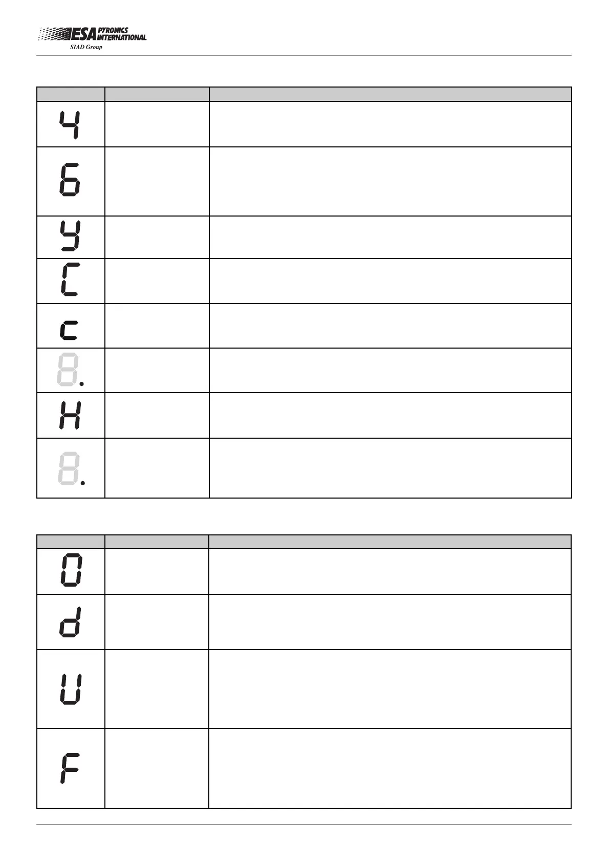
DISPLAY STATUS DESCRIPTION
FIXED
Regime phase for ESA ESTRO-B with only 2nd stage burner on. The instru-
ment intercepts the 1st stage solenoid valve. This phase occurs only when the
“1st stage gas outlet type” parameter is programmed on “Interrupted”.
FIXED
Regime phase with air valve on. In case the “Air pressure switch parameter” is
programmed on “Lockout o Waiting" the instrument waits for the pressure
switch signal before indicating this phase, whilst if “Disable” is programmed the
transition to this phase corresponds with the activation of the air valve . This
phase occurs only when the “Air flow control mode” parameter is programmed
on “Discontinue or Pulse”.
FIXED
Detection system check phase in which the instrument verifies that the flame is
extinguished in a maximum time of 20 seconds after burner shut down, other-
wise there is lockout for illegal flame.
FIXED
Chamber cooling phase with maximum air flow. In applications with three-posi-
tion air valve, the air valve is brought to maximum opening . During this phase
flame absence is checked otherwise lockout is determined due to illegal flame.
FIXED
Chamber cooling phase with minimum air flow. In applications with three-posi-
tion air valve, the air valve is driven to the minimum opening . During this phase
flame absence is checked otherwise lockout is determined due to illegal flame.
FIXED
DOT
Chamber purging or waiting phase following burner shut down. During this
phase the instrument does not accept any command and displays the phase or
lockout code that caused shut down, besides the fixed decimal point.
FIXED
Stop phase for regulation requested by serial communication. The instrument
keeps the burner off, waits for an ignition command, forces the air shutter to
close and deactivates all the other outputs.
FLASHING
DOT
High temperature functioning on. During this operation the instrument displays
the lockout or phase code, besides the flashing decimal point. If the high tem-
perature function provides only the prepurge exclusion, this indication is pre-
sent in all the phases prior to the ignition of the burner.
DISPLAY STATUS DESCRIPTION
FLASHING
Manual stop generated by the operator via the local or remote button when the
burner is in a normal operation phase. The instrument keeps the burner off and
waits for the unlock that can be given by local button, remote button or serial
communication.
FLASHING
Lockout due to the detection of an illegal flame, during the phases before the
burner ignition phase or after the shut down phase. The causes can be found
in the detection system (broken probe or presence of humidity in UV-2) or in a
gas leakage from the solenoid safety valve that allows the burner to remain on.
FLASHING
Lockout due to the missing flame formation during 1st gas stage burner igni-
tion. The causes can be found in the ignition system (no spark from the elec-
trodes or broken transformers), in the bad flow regulation of fuel and combu-
stion agents, or in the detection system (broken probe, interrupted cables,
ground not connected). Specifically, in the first two cases the flame does not
ignite, whilst in the last case the flame forms but ESA ESTRO is unable to
detect it.
FLASHING
Lockout due to the flame signal loss during normal burner operation. The cau-
ses can be found in the flow regulation of combustion air and fuel (rapid flow
variations, regulation out of allowed range). Furthermore, this lockout condition
is due to malfunctioning of the sensibility probe dimming shutter when perma-
nent operation is on with UV detection, if this does not open after the hourly
check.
Lockout or failure
 Loading...