SiAECOSYS V2
2. Controller connection
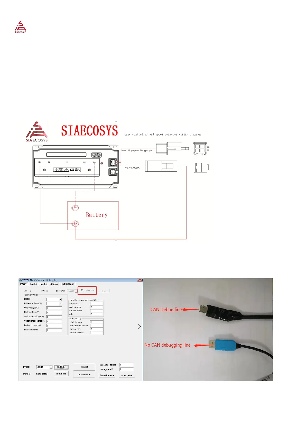
2.1 Connect controller
Controller host computer simple wiring diagram
Description: controller B+ connects battery B+ controller B-connects battery B-, controller electric door locks connect
battery or controller B+;
The USB debug line is connected to the controller debug port;
2.1.1 According to the controller with CAN or without CAN to select the appropriate USB debug line; with CAN controller
need to check the CAN enable, without CAN does not need to check; EM200 controller needs to exchange the debug line
CAN-H and CAN- L , otherwise can’t connect the controller;
 Loading...