5.4 Meter display and MENU descriptions
Please skip this section for flow sensor products.
5.4.1. Meter display and function keys
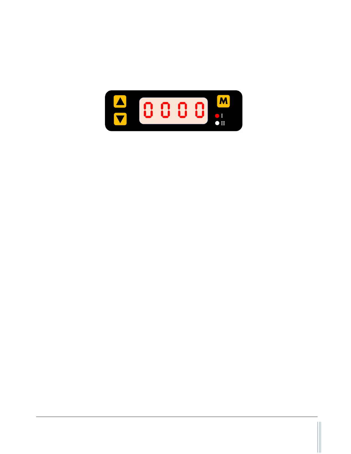
Figure 5.1: MF4o00 display and function keys
The meter has a front 3-key board for the user to set the desired functions, access data, and check
for the status. The Menu key (M) is at the upper right position that allows the user to select a function
and confirmation or other related actions that will be detailed described in the MENU key sequence
graphic presentation. Two keys (“Up” and “Down”) are used to select the functions. The two LED
lights (I and II) are used for the indication of display contents. For the default instant flow rate display,
both of these two LEDs will be off. Please refer to the detailed information below.
The default instant flow rate is SLPM with 4 digits, one of the digits is a decimal. When the flow rate
is above the specified flow range, LED I will flash for the flow rates above the upper limit, and LED II
will flash for the flow rates below the lower limit. If both LEDs are flashing, the displayed values are
incorrect.
Once the power is supplied and no abnormal issues are observed, the meter is ready to perform the
measurements. While the LED displays the instant mass flow rate, the accumulated or totalized flow
rate can be accessed by press the “Up” or “Down” key. The accumulated flow rate is registered with
“standard liter” (SL), and the maximum can be 99,999,999 SL. The first four digits of the
accumulated flow rate are indicated by the “I” LED light, and the last four digits are represented when
the “II” LED light is on. The “I” and “II” LED lights will be automatically switched when the
accumulated flow rate is displayed. The accumulated flow rate will be automatically saved every
three minutes. At the time of the power failure or cut-off, the value will be representing the latest
saved ones.
5.4.2. MENU function input sequence
At the flow measurement (main) display, press the three MEMU keys, it will allow the user to perform
a variety of settings of the product. The following graph details the key sequence for each function,
and some detailed explanations are followed after the graphic presentation.