EasyManuals Logo

Siargo MF4000 User Manual

Siargo MF4000
34 pages
To Next Page IconTo Next Page
To Previous Page IconTo Previous Page
Page #8 background imageLoading...
Page #8 background image
www.Siargo.com MF / FS4000 User Manual 7 | P a g e
3. Knowing the products
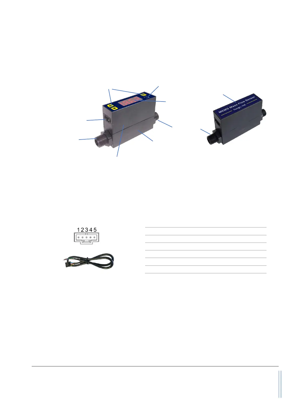
3.1. Product description
Figure 3.1: MF/FS4000 parts description
3.2. Power and data cable description
Table 3.1: MF/FS4o00 pin/wire assignments.
Figure 3.2: MF/FS4o00 connection and cable
Note: 1. The standard cable has an AMPMODU MTE (5 positions) compatible connector with a length of 0.5
meters.
2. The RS485 Modbus is asynchronous, half-duplex communication. When the data are transmitted
or received from the product, the other pin is serving as the ground.
3. The RS232 communication is bi-directional. TX is the transmit pin that sends data from the product.
RX is the receive pin.
Wire
Color
Definition
1
Blue
RS485B / RS232 TX
2
Green
Analog output, 0.5~4.5Vdc
3
Red
Power supply, 8 ~ 24Vdc
4
Black
Ground
5
Yellow
RS485A / RS232 RX
Exchangeable
connector
MENU keys
Excahngeable
connector
Flow direction
Electrical interface, AMP
MTE, 5 positions
Meter body
Sensor body
Status indicator

Questions and Answers:

Question and Answer IconNeed help?

Do you have a question about the Siargo MF4000 and is the answer not in the manual?

Siargo MF4000 Specifications

General IconGeneral
BrandSiargo
ModelMF4000
CategoryMeasuring Instruments
LanguageEnglish

Related product manuals