B06 20 243 E-EN
page 19 / 23
09.2010
Installation and Maintenance Manual
CB8-E
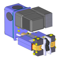
6. Turn the threaded borehole inside the free wheel ring into the upper position by pumping the
adjusting nut with the hexagon key Ø4 mm. Mount threaded pin (figure 12).
Fig. 12: Handling of the readjusting unit
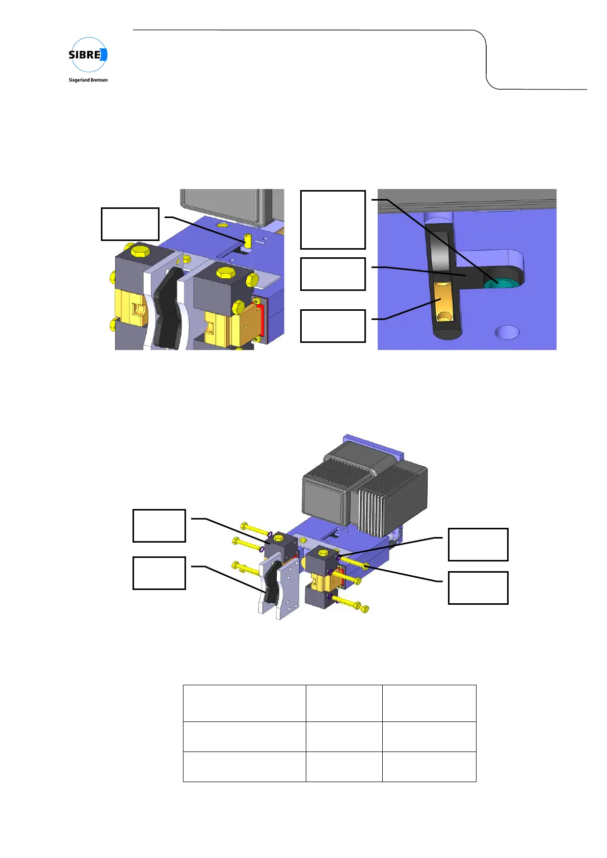
7. Loosen the bolts for the brake linings on the brake shoes. The linings can be removed upwards,
downwards or in front direction (figure 13).
Fig. 13: Replacing the brake linings
8. Put new linings on the brake shoes and fix them with bolts and locking washers .
Mounting bolts for
linings CB8-M3-50
Mounting bolts for
linings CB8-M4-100
Fig. 14: Tightening torque for mounting bolts
free wheel
ring with
threaded
borehole