3 # 88011155/YTW9/2016-03 © SICK AG · Germany · All rights reserved · Subject to change without notice · Irrtümer und Änderungen vorbehalten
6. Electrical Installation
6.1 Data Interfaces
Recommended cable length from ID sensors to host:
LED Farbe Funktion
Power grün Leuchtet, wenn die Versorgungsspannung am
(Codeleser 1) CDM420 anliegt und Schalter S 1 auf „ON“
Sensor 1, 2 gelb Leuchtet, wenn der entsprechende Eingang des
Sen 1,2 ID-Sensors 1 oder 2 schaltet
Result 1, 2 gelb Leuchtet, wenn der entsprechende Ausgang des
Res 1,2 ID-Sensors 1 oder 2 schaltet
6. Elektrische Installation
6.1 Datenschnittstellen
Empfohlene Leitungslänge der ID-Sensoren zum Host:
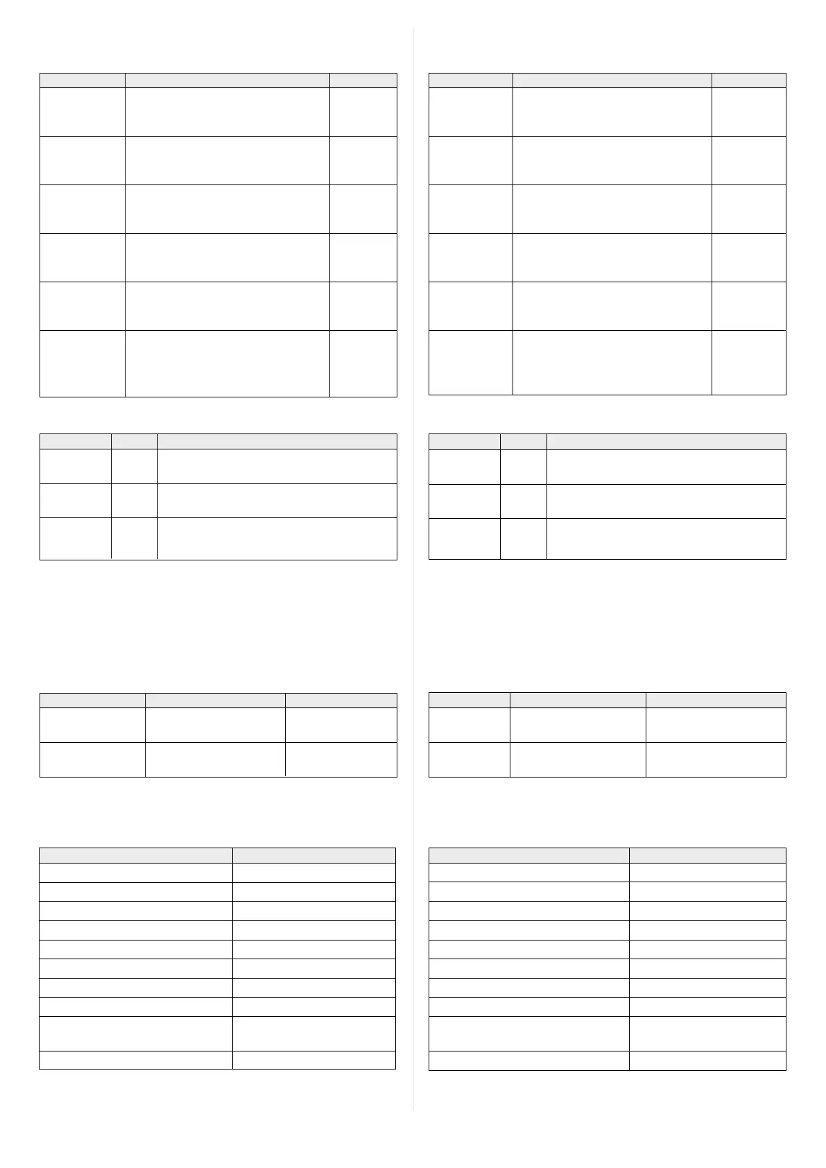
5.3 Function of LEDs (connecting board 1 and 2)
LED Color Function
Power green Lights up when the power supply is connected
(reader 1) to the CDM420 and switch S 1 is set to “ON“
Sensor 1, 2 yellow Lights up when the corresponding input of the
Sen 1,2 ID sensor 1 or 2 switches
Result 1, 2 yellow Lights up when the corresponding output of the
Res 1,2 ID sensor 1 or 2 switches
Interface type Data transfer rate Distance to host
RS 232 Up to 19.2 kBd Max. 10 m
38.4 kBd ... 57.6 kBd Max. 3 m
RS 422/485 Max. 38.4 kBd Max. 1,200 m
Max. 57.6 kBd Max. 500 m
Schnittstellentyp Datenübertragungsrate Entfernung z. Host
RS-232 Bis 19,2 kBd Max. 10 m
38,4 kBd... 57,6 kBd Max. 3 m
RS-422/485 Max. 38,4 kBd Max. 1.200 m
Max. 57,6 kBd Max. 500 m
5. Kongurationselemente und Anzeigen
5. 1 Kongurationsschalter für ID-Sensor 1 (Anschlusskarte 1)
Schalter Funktion Default
S 1 (Power) Anliegende Versorgungsspannung: ON
ON: Versorgungsspannung ein
OFF: Versorgungsspannung aus
S 2 (RS-485) RS-422/485-Umschaltung: OFF
ON: RS-485
OFF: RS-422
S 3 (Trm - 422) RS-422-Terminierung (Empfänger): OFF
ON: Widerstand 120 Ohm zugeschaltet
OFF: Keine Terminierung
S 4 (Trm - CAN) Terminierung der CAN-Schnittstelle: OFF
ON: Widerstand 120 Ohm zugeschaltet
OFF: Keine Terminierung
S 6 (SGND-GND) Bezugspotenzial für Sensor-GND: ON
ON: Verbunden mit GND des ID-Sensors
OFF: Potenzialfrei
S 8 (NO CMC) Integration des CMC600 (ID-Sensor 1): NO (oben)
„YES“: CMC in Leitung der Aux-Schnitt-
stelle des ID-Sensors 1 geschaltet
„NO“: Kein CMC gesteckt
5. Conguration Elements and Displays
5.1 Conguration switches for ID sensor 1 (connecting board 1)
Switch Function Default
S 1 (Power) Connected power supply: ON
ON: Power supply on
OFF: Power supply off
S 2 (RS 485) RS 422/485 selector: OFF
ON: RS 485
OFF: RS 422
S 3 (Trm422) RS 422 termination (receiver): OFF
ON: 120 Ohm resistor connected
OFF: No termination
S 4 (TrmCAN) Termination CAN interface: OFF
ON: 120 Ohm resistor connected
OFF: No termination
S 6 (SGND-GND) Reference potential for ID sensor GND: ON
ON: Connected to ID sensor’s GND
OFF: Floating
S 8 (NO CMC) CMC 600 integration (ID sensor 1): NO (on top)
“YES”: CMC connected to Aux interface
of ID sensor 1
“NO”: CMC not connected
5. 2 Funktion der LEDs (Anschlusskarte 1 und 2)
6.2 Versorgungsspannung
Die Höhe der erforderlichen Versorgungsspannung ist abhängig
vom anzuschließenden ID-Sensor und der optionalen Module:
Wichtig:
ID-Sensor 1: Die zusätzlichen Eingänge Aux In 1 und 2 sowie die
Ausgänge Aux Out 1 und 2 haben keine Statusanzeige durch LEDs.
Important:
ID sensor 1: The additional inputs Aux In 1 and 2 as well as the
outputs Aux Out 1 and 2 have no status indication by LEDs.
Siehe hierzu auch Angaben auf dem Typenschild des ID-Sensors.
*) Nr. 2056475 (mit Leitung 0,2 m) oder Nr. 2057709 (mit Leitung 0,3 m).
6.2 Supply voltage
The required power supply voltage depends on the ID-sensor to be
connected on the used optional modules:
See also details on the typeplate of the ID sensor.
*) No. 2056475 (with cable 0.2 m) or No. 2057709 (with cable 0.3 m).
ID-Sensor / Modul Versorgungsspannung
CLV61x, CLV62x, Lector62x DC 10 V ... 30 V
CLV63x ... CLV65x ohne Heizung DC 18 V ... 30 V
CLV63x ... CLV65x mit Heizung DC 24 V ± 10 %
RFH6xx, RFU620-104xx DC 10 V ... 30 V
RFU620-101xx, bis –25 °C DC 10 V ... 30 V
RFU620-101xx, bei –25 °C ... –35 °C DC 20 V ... 30 V
CLV42x ... CLV45x, ICR85x-2 DC 10 V ... 30 V
ICR84x-2 DC 15 V ... 30 V
IDM1xx, IDM2xx DC 5 V, über DC 24 V/5 V-
Wandler
*)
Mit CMF400 oder CMD400 DC 18 V ... 30 V
ID sensor /Module Supply voltage
CLV61x, CLV62x, Lector62x 10 V to 30 V DC
CLV63x ... CLV65x without heater 18 V to 30 V DC
CLV63x ... CLV65x with heater 24 V DC ± 10 %
RFH6xx, RFU620-104xx 10 V to 30 V DC
RFU620-101xx, down to –25 °C 10 V to 30 V DC
RFU620-101xx, from –25 °C to –35 °C 20 V to 30 V DC
CLV42x ... CLV45x , ICR85x-2 10 V to 30 V DC
ICR84x-2 15 V to 30 V DC
IDM1xx, IDM2xx 5 V DC, via 24 V DC/5 V DC
converter
*)
With CMF400 or CMD400 18 V to 30 V DC

 Loading...


