7 # 88011155/YTW9/2016-03 © SICK AG · Germany · All rights reserved · Subject to change without notice · Irrtümer und Änderungen vorbehalten
8. Technical Data
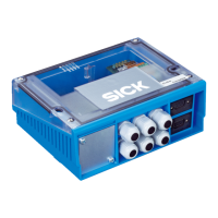
Type CDM420-0004 (No. 1028487)
Visual indicators 10 x LED
Electrical connections 2 x female connector, D-Sub HD, 15-pin
2 x male connector, D-Sub, 9-pin
Screw terminals, for cores 0.14 mm
2
... 2.5 mm
2
(approx. 26 AWG ... 13 AWG)
Spring terminals, for cores 0.14 mm
2
... 1 mm
2
(approx. 26 AWG ... 17 AWG)
Cable glands 6 x M16, for cables ∅ 4.5 mm ... 10 mm
Power supply voltage 10 V ... 30 V DC, SELV respectively PELV to
IEC 60364-4-41.
18 V ... 30 V DC when using the CMD400 display
module and/or a CMF400 eldbus module.
Use a power supply unit according to Class 2
(UL1310)
Power down stream
1)
2 x P
ID sensor
+ internal power consumption 0,5 W
Fuse
2)
2 x glass tube fuse 0.8 A, slow-blow
Housing / Color Polycarbonate / blue, transparent cover
Conformity CE, UL
3)
Protection class III
4)
, to EN 61140
Enclosure rating IP 65
5)
, to EN 60529
1) ID sensor type specic, without display module, parameter cloning module or
eldbus module.
2) For voltage +24 *, switched via S 1 and internal fuse.
3) Valid with corresponding product marking on the typeplate.
4) Class I with CMP490 power supply module and connected PE conductor.
5) With SICK standard cables and closed face plate (dummy plate without connec-
tions or plate with IP 65 connectors) on the CDM420.
7. Fehlersuche für Basisgerät CDM420
7. Troubleshooting for CDM420 (Basic Device)
Wichtig:
Fehlersuche in Zusammenhang mit optionalen Modulen siehe
jeweils deren Betriebs- oder Montageanleitung.
Important:
For troubleshooting of the optional modules see the respective
operating or tting instructions.
*) CLV-Setup für CLV42x bis CLV45x sowie ICR84x-2/85x-2.
SOPAS-ET nicht anwendbar für Handheldscanner IDM1xx und IDM2xx.
*) CLV-Setup for CLV42x to CLV45x as well as ICR84x-2/85x-2.
SOPAS-ET not applicable for IDM1xx and IDM2xx hand-held scanners.
Remedy
• Set switch S 1 (Power) to “ON”
• If no CMC600 is connected, set
switch S 8 to “NO”
• SOPAS-ET
*)
software: required de-
vice descrciption le for the related
ID sensor not existent or le related
to an other rmware version as the
current device uses.
Reload and insert the suitable
device descrciption le in SOPAS-
ET using the “Device manager”
function.
• SOPAS-ET
*)
:Using the “Device
search” function to start the com-
munication with the ID sensor
• Connect reading pulse sensor in
accordance with the operating
instructions of the ID sensor
• Check switch S 6 (SGND–GND)
• Using SOPAS-ET
*)
software, set
the reading pulse source on the ID
sensor to “Sensor 1”.
Perform a download to the ID
sensor.
Malfunction
• “Power” LED (U
IN
*) does not
light up when power supply U
IN
is connected
• Cannot access ID sensor with
SOPAS-ET
*)
conguration soft-
ware after connecting the PC to
the “AUX” male connector
• Signals from connected reading
pulse sensor have no effect to
the ID sensor
Abhilfe
• Schalter S 1 (Power) in Position
„ON“ bringen
• Wenn kein CMC600 gesteckt, Schal-
ter S 8 in Position „NO“ bringen
• SOPAS-ET
*)
: Erforderliche Gerätebe-
schreibungsdatei für betreffenden
ID-Sensor nicht vorhanden oder für
anderen Firmwarestand als vorlie-
gendes Gerät.
Passende Gerätebeschreibungs-
datei in SOPAS-ET über Funktion
„Gerätemanager“ nachladen und
einbinden.
• SOPAS-ET
*)
: Mit Funktion „Geräte-
suche“ die Kommunikation mit dem
ID-Sensor aufnehmen
• Lesetakt-Sensor gemäß Betriebsan-
leitung des ID-Sensors anschließen
• Stellung des Schalters S 6 prüfen
(SGND–GND)
• Mit SOPAS-ET
*)
die Quelle des
Lesetakts im ID-Sensor auf „Sensor
1“ einstellen.
Download zum ID-Sensor durchfüh-
ren!
Störung
• Nach Anlegen der Versorgungs-
spannung U
IN
leuchtet die LED
„Power“ (U
IN
*) nicht
• Nach Anschluss des PCs an
den Stecker „AUX“ kein Zugriff
auf den ID-Sensor mit Kongu-
rationssoftware SOPAS-ET
*)
• Signale des angeschlossenen
Lesetakt-Sensors bleiben
wirkungslos im ID-Sensor
8. Technische Daten
Typ CDM420-0004 (Nr. 1028487)
Optische Anzeigen 10 x LED
Elektrische Anschlüsse 2 x Dose, D-Sub-HD, 15-pol.
2 x Stecker, D-Sub, 9-pol.
Schraubklemmen, für Adern 0,14 ... 2,5 mm
2
Federkraftklemmen, für Adern 0,14 ... 1 mm
2
Leitungsverschraubungen 6 x M16, für Leitungen ∅ 4,5 mm ... 10 mm
Versorgungsspannung DC 10 V ... 30 V, SELV bzw. PELV nach
IEC 60364-4-41.
DC 18 V ... 30 V bei Verwendung des
Display-Moduls CMD400 und/oder
eines Feldbusmoduls CMF400.
Verwendung eines Netzteils gemäß Class 2
(UL1310)
Leistungsdurchuss
1)
2 x P
ID-Sensor
+ Eigenleistungsaufnahme 0,5 W
Sicherung
2)
2 x Glasrohrsicherung 0,8 A träge
Gehäuse / Farbe Polycarbonat / Blau, Deckel transparent
Prüfzeichen CE, UL
3)
Schutzklasse III
4)
, nach EN 61140
Schutzart IP 65
5)
, nach EN 60529
1) Abhängig vom ID-Sensor, ohne Display-Modul, Parameterspeicher-Modul oder
Feldbusmodul.
2) Für Spannung +24 *, geschaltet über S1 und interne Sicherung.
3) Gültig bei entsprechender Gerätekennzeichnung auf dem Typenschild.
4) Klasse I mit Power-Supply-Modul CMP490 und angeschlossenem PE-Leiter.
5) Bei Verwendung der SICK Standardanschlussleitung und geschlossener Frontblen-
de des CDM420 (Blindplatte ohne Anschlüsse oder Platte mit IP-65-Anschluss).

 Loading...