53
8012428/YWL2/3-0/2016-08| SICK O P E R A T I N G I N S T R U C T I O N S | DUSTHUNTER T
Subject to change without notice
ASSEMBLY AND INSTALLATION 3
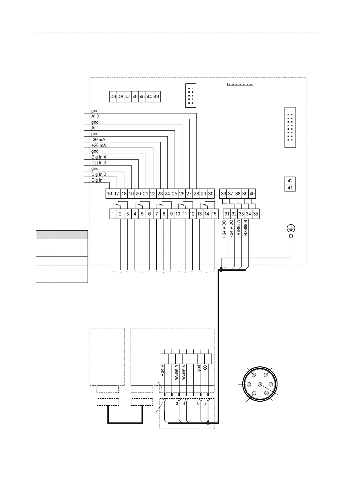
3.3.4.4 Standard connection
Fig. 31: Standard connection
MCU processor board
White
Brown
Green
Yellow
White
Yellow
Green
Brown
Plug assignment
(View on pin side)
RS485 B
3
RS485 A
4
5
6
-24 V
2
7
1
+24 V
Switching position of the
relay contacts in current-
less condition
Maintenance
Operation/
failure
Reflector
DHT-R1x
(only DUST-
HUNTER T200)
Plug
SICK line
Connection line
(SICK line or onsite line accord-
ing to see “General information,
prerequisites”, page 47)
Sender/receiver unit
Function check
Socket
Socket
Socket
Plug
Plug
Maintenance
Function
check
Maintenance
request
Limit value
Relay Terminal
1 1, 2, 3
2 4, 5,6
3 7, 8, 9
4 10, 11, 12
5 13, 14, 15
 Loading...