7.2 Pin assignment
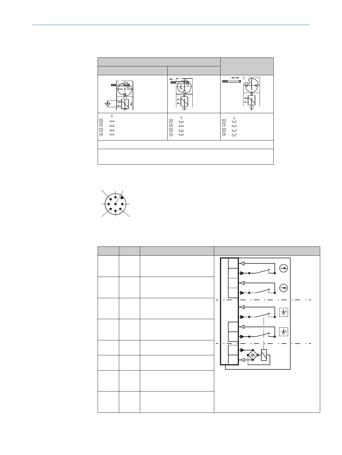
Table 2: Switching elements and switching functions
Actuator inserted Actuator removed
Locked Unlocked
Contact pair 41/42 not assigned.
E1: +24 V DC magnet coil voltage supply (locking device)
E2: +0 V DC ma
gnet coil voltage supply (locking device)
7.3 System connection (M12, 8-pin)
Figure 1: System connection (M12, 8-pin)
Table 3: System connection pin assignment (M12, 8-pin)
Pin Contact Description
1 21 Positive opening normally
closed contact input for locking
device monitoring
1
2
3
8
2
31 32
11 12
41 42
21 22
1
7
4
3
5
6
1
Door monitoring
2
Locking device monitoring
3
Locking device control
2 22 Positive opening normally
c
losed contact output for lock‐
ing device monitoring
3 11 Positive opening normally
closed contact input for door
monitoring
4 12 Positive opening normally
c
losed contact output for door
monitoring
5 E1 +24 V DC magnet coil voltage
supply (locking device)
6 E2 +0 V DC magnet coil voltage
supply (locking device)
7 31 Positive opening normally
c
losed contact input for door
monitoring
8 32 Positive opening normally
closed contact output for door
monitoring
b
P
ay attention to tightness of the plug connector.
7 ELE
CTRICAL INSTALLATION
16
O P E R A T I N G I N S T R U C T I O N S | i10 Lock 8022168/2017-11-14 | SICK
Subject to change without notice