Do you have a question about the SICK i110 and is the answer not in the manual?
Defines the scope of the operating instructions for the i110 Lock safety locking devices.
Points to further resources and information available online, such as data sheets and CAD drawings.
Explains the meaning of symbols and conventions used throughout the operating instructions.
Provides essential safety guidelines that must be followed for the correct configuration and operation of the device.
Specifies the intended application of the safety locking device in conjunction with guards and machine controllers.
Outlines the necessary qualifications and expertise for personnel involved in project planning, installation, and operation.
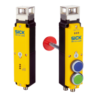
Explains the basic setup and operational principles of the i110 Lock as an interlocking device.
Details the key features, variants, and locking principles of the safety locking device.
Lists and explains the specific symbols found on the i110 Lock product.
Describes the procedure for manually unlocking the safety locking device in certain situations.
Discusses the obligations and safety considerations for the machine manufacturer when implementing the device.
Outlines the responsibilities and safety measures for the machine operator during device use.
Covers design considerations for the safety locking device, including preventing tampering and ensuring effectiveness.
Details how to properly integrate the safety locking device into the machine's electrical control system.
Specifies requirements for testing the device during commissioning, after modifications, and at regular intervals.
Highlights critical safety precautions to be observed during the mounting process.
Explains the procedure for converting or adjusting the actuating head of the device.
Provides step-by-step instructions for the correct physical mounting of the safety locking device.
Advises on measures to protect the device from foreign bodies and environmental factors.
Emphasizes essential safety measures to be followed during the electrical installation of the device.
Details the pin assignments for switching elements and functions for various device variants.
Explains the system connection details for the M12, 8-pin connector type.
Describes the procedure for establishing a system connection using a cable entry.
Outlines the procedures for performing functional tests after installation and after any fault.
Specifies requirements for periodic maintenance and technical checks to ensure ongoing proper function.
Provides guidelines for the proper disposal of unusable devices in accordance with national regulations.
Lists detailed technical specifications, features, and electrical data for the i110 Lock device.
Presents mechanical dimensions and drawings for the i110 Lock and its actuator.
Provides detailed ordering information, including type codes and part numbers for different device configurations.
Lists the available actuator types, their actuation options, and specifications.
Details additional accessories such as cables, nodes, and locking mechanisms.
Declares the product's conformity with relevant EU directives and standards.