1
2
3
2
31 32
11 12
41 42
21 22
1
8
7
4
3
5
6
8
2
3
1 32
11 12
41 42
21 22
1
7
4
3
5
6
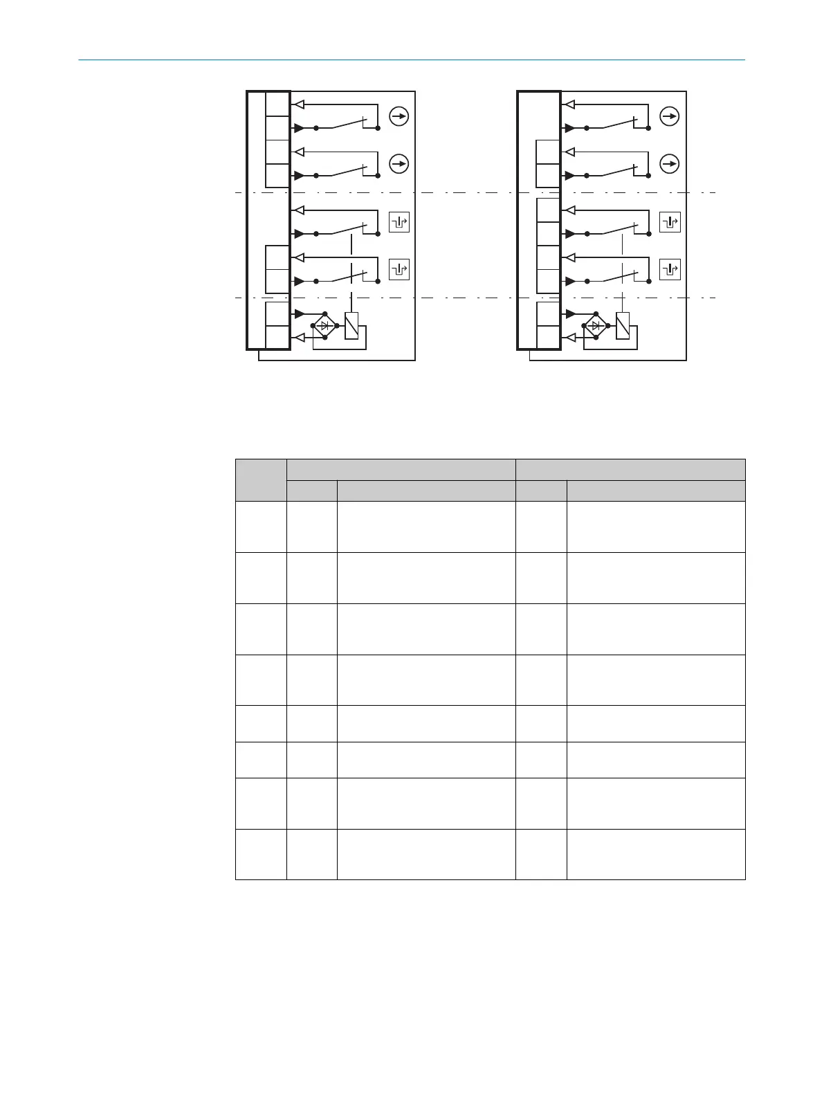
1
Door monitoring
2
Locking device monitoring
3
Locking device control
Table 3: System connection pin assignment (M12, 8-pin)
Pin i110-*0354 i110-*0454
Contact Description Contact Description
1 21 Positive opening normally
c
losed contact input for locking
device monitoring
11 Positive opening normally
closed contact input for door
monitoring
2 22 Positive opening normally
c
losed contact output for lock‐
ing device monitoring
12 Positive opening normally
closed contact output for door
monitoring
3 11 Positive opening normally
closed contact input for door
monitoring
21 Positive opening normally
closed contact input for locking
device monitoring
4 12 Positive opening normally
c
losed contact output for door
monitoring
22 Positive opening normally
closed contact output for lock‐
ing device monitoring
5 E1 +24 V DC magnet coil voltage
supply (locking device)
E1 +24 V DC magnet coil voltage
supply (locking device)
6 E2 +0 V DC magnet coil voltage
supply (locking device)
E2 +0 V DC magnet coil voltage
supply (locking device)
7 31 Positive opening normally
c
losed contact input for door
monitoring
41 Positive opening normally
closed contact input for locking
device monitoring
8 32 Positive opening normally
closed contact output for door
monitoring
42 Positive opening normally
closed contact output for lock‐
ing device monitoring
b
P
ay attention to tightness of the plug connector.
6.4 System connection (cable entry)
1. Open desired insertion opening with a suitable tool.
2. Mount the cable gland with corresponding enclosure rating.
3. Connect contacts (contact assignment see table 2).
6 ELE
CTRICAL INSTALLATION
18
O P E R A T I N G I N S T R U C T I O N S | i110 Lock 8020543/17K9/2020-06-08 | SICK
Subject to change without notice