6.2 Pin assignment
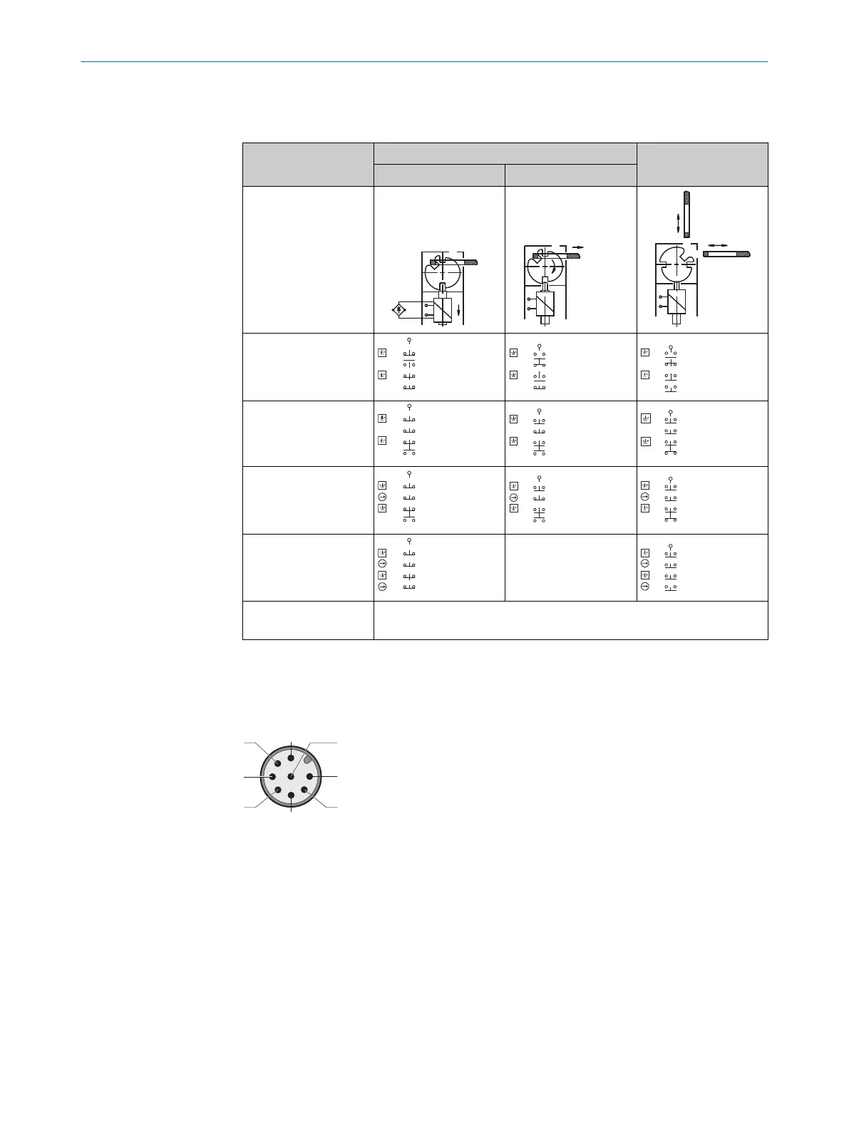
Table 2: Switching elements and switching functions
Actuator inserted Actuator removed
Locked Unlocked
i110-*0233
i110-*0253
i110-*0313S06
i110*0453
i110-*0454
1)
i110-*0354
2)
All variants E1: +24 V DC magnet coil voltage supply (locking device)
E2: +0 V DC ma
gnet coil voltage supply (locking device)
1)
Contact pair 31/32 not assigned.
2)
Contact pair 41/42 not assigned.
6.3 System connection (M12, 8-pin)
Figure 2: System connection (M12, 8-pin)
ELECTRICAL INSTALLATION 6
8020543/17K9/2020-06-08 | SICK O P E R A T I N G I N S T R U C T I O N S | i110 Lock
17
Subject to change without notice