connected; to do this, follow the steps below.
3. Scan the Quick Pair barcode on the base station.
✓ The status indicator on the hand-held scanner lights up permanently in red.
✓ A short audible signal sounds which confirms that the connection process
has been activated. The scanner continuously emits short clicks and the
scanner's connection indicator flashes blue at short intervals during the con‐
nection process. The connection process is complete when four ascending
audible signals sound. The operating indicator on the smart base station
lights up permanently in blue.
✓ If the hand-held scanner is removed from the smart base station, the
connection indicator on the hand-held scanner flashes blue once every
2.5seconds.
If the connection process for the mobile handheld scanner was not success‐
ful, the error is indicated by two audible signals (di-do di-do). The hand-held
scanner is automatically reset to the “Uninstall” status.
4. Scan the required code for the quick setup of the host interface to complete
the installation, see Quick setup of host interface, page 2.
The default setting for the host interface of the smart base station is USB
HID. To use USB COM, the virtual USB COM software driver (available at
www.sick.com) must be installed on the host device before using the scan‐
ner.
4.5 Using HID mode
NOTE
The procedure described below is based on a typical Windows environment.
The installation process may vary depending on the remote host device,
operating system, and Bluetooth driver.
✓ The rechargeable battery is fully charged.
✓ The connection indicator on the hand-held scanner flashes red and green
alternately (“Uninstall” status).
If the hand-held scanner is not set to the “Uninstall” status:
b
To disconnect the connection, scan the Uninstall configuration code.
NOTE
If the remote host has the current Bluetooth drivers or if it is an iOS or
Android device, HID mode is recommended in order to establish a fast con‐
nection (HID mode configuration mode).
If you encounter problems with HID mode, use the conventional HID mode
instead (HID legacy mode configuration code).
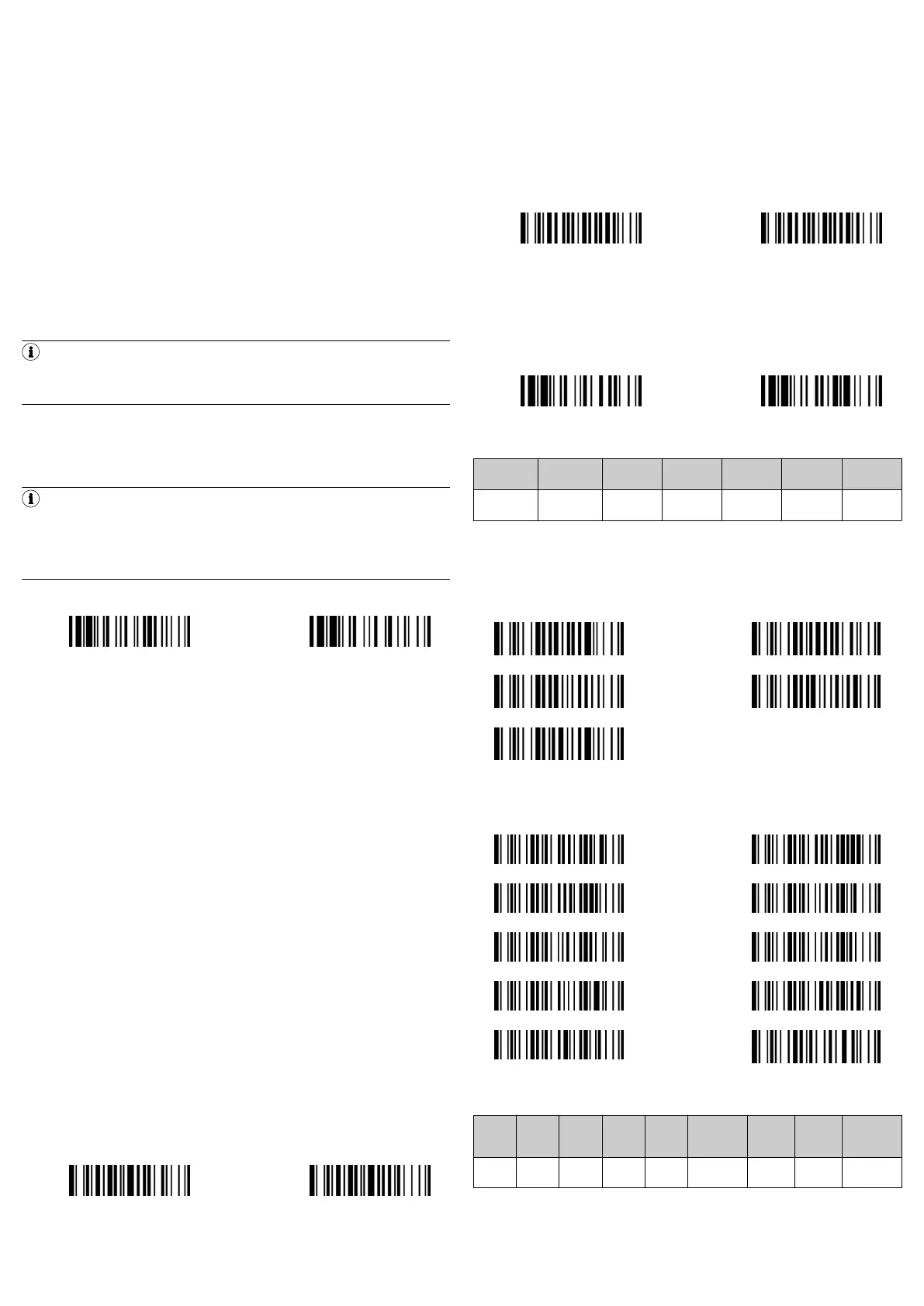
1. Scan the required configuration code:
HID mode HID legacy mode
✓ The connection indicator on the hand-held scanner flashes blue three times
every 2seconds if the hand-held scanner is not on the smart base station.
2. Perform a search for Bluetooth-enabled devices via the Bluetooth host.
3. Select “IDMxxx” from the list of devices found.
If the host device prompts you to enter a PIN code or authorization key:
b
Enter “00000000” (default) and then select “Keyboard on IDMxxx”.
✓ The connection process is complete when four ascending audible signals
sound.
✓ The connection indicator on the scanner flashes blue once every 2.5sec‐
onds if the hand-held scanner is not on the smart base station.
If the hand-held scanner is not connected to the host device within 1minute of
scanning the configuration code, the hand-held scanner is automatically set to
sleep mode. To continue with the installation from sleep mode, the trigger on the
hand-held scanner must be actuated.
4.6 IDM Set Up Tool software
The IDM Set Up Tool 4.0 software is a Windows-based configuration software
package for IDM hand-held scanners. Configuration via the software is an alterna‐
tive to the configuration described below, which involves scanning configuration
codes.
The software can be downloaded free of charge at www.sick.com. The IDM oper‐
ating instructions contain a detailed description of the configuration using the IDM
Set Up Tool software.
4.7 Out-of-range scanning
If there is a wireless connection between the scanner and remote host device, the
hand-held scanner transmits all scanned code data directly after scanning the bar
code. The hand-held scanner is however preset so that it is not possible to scan
bar code data if the wireless connection to the remote host device is lost.
If the function for out-of-range scanning is activated, the hand-held scanner can
continue scanning bar code data outside the wireless range. All scanned data
is temporarily stored in the internal memory until the wireless connection is
restored.
b
To activate/deactivate the function, scan one of the following configuration
codes:
Enable out-of-range
scanning
Disable out-of-range
scanning ◆
If the hand-held scanner is outside the scanning range, four descending audible
signals indicate that the wireless connection has been interrupted. The connec‐
tion indicator on the hand-held scanner flashes blue three times every 2 seconds.
Once the hand-held scanner is back within the wireless range, four ascending
audible signals indicate that the wireless connection has been restored. The
hand-held scanner flashes blue once every 2.5seconds. If the “Out-of-range
scanning” function is activated, all scanned data that has been temporarily stored
is transmitted automatically.
4.8 Presentation scanning
Presentation scanning (hand-held scanner detects bar codes automatically and
reads these in without actuating the trigger) is intended for hands-free applica‐
tions. If the auto-sense function is activated, the hand-held scanner switches to
presentation mode as soon as it is placed on the smart base station (only in
conjunction with devices from the IDMx41 product family) or in the presentation
stand.
b
To activate/deactivate the function, scan one of the following configuration
codes:
Enable auto-sense Disable auto-sense ◆
4.9 Sleep mode and power off
The hand-held scanner is preset so that it switches to sleep mode if it is not used
for a certain period of time. If the hand-held scanner is in “sleep mode” and is not
reactivated after a certain period of time, it switches automatically to the “power
off” status. Both statuses can also be activated by scanning a configuration code.
The scanner can be reactivated by actuating the trigger.
b
To activate the function, scan one of the following configuration codes:
Sleep mode Power off
4.10 Quick setup of keyboard interface
The characters are output via the keyboard interface in the following sequence:
Preamble Data length Prefix ID
Scanned
data
Suffix ID Postamble
Data set
suffix
1–15
characters
2–4
characters
1 or 3
characters
Variable 1 or 3
characters
1–15
characters
1
character
To make a quick change to the data set suffix when using the keyboard interface
(USB), the configuration codes shown below can be used. Information on config‐
uring other segments of the sequence, such as preamble or postamble, can be
found in the operating instructions.
4.10.1 Data set suffix
None RETURN ◆
TAB SPACE
ENTER
4.10.2 Keyboard layout
The USA keyboard layout is set as default. To change the layout to another
country, scan one of the codes below.
USA ◆ France
Germany Canadian French
United Kingdom-UK Spain
Latin America Netherlands
Japan Sweden/Finland
4.11 Quick setup of serial interface
The characters are output via the serial interface in the following sequence:
STX
Pream‐
ble
Data
length
Prefix
ID
Scan‐
ned
data
Suffix ID
Post‐
amble
ETX
Data set
suffix
1 char 1–15
chars
2–4
chars
1 or 3
chars
Variable 1 or 3
chars
1–15
chars
1 char 1 char
To quickly change the data set suffix when using the serial interface (RS-232 or
USB COM port), the configuration codes shown below can be used. Information on
configuring other segments of the sequence, such as preamble or postamble, can
be found in the operating instructions.
8028120//2022-10-28/en IDM Bluetooth (IDMxx1-4xx) | SICK 3
 Loading...