If these instructions are not complied with, the IP enclosure rating for the device is not
guaranteed!
5.2 Note on the swivel connector
NOTICE
Damage to the connector unit from over-tightening!
The connector unit on the device has two opposite end positions.
■
Do not rotate the connector unit from either of the two end positions by more than
180°.
5.3 Pin assignment of the connections
NOTE
The function of pin 2 depends on the teach-in variant, if the pin 2 configuration is set to
AUTO (factory setting).
NOTE
Pin 5 can only be assigned with L/D if L/D is set to AUTO in the defaults.
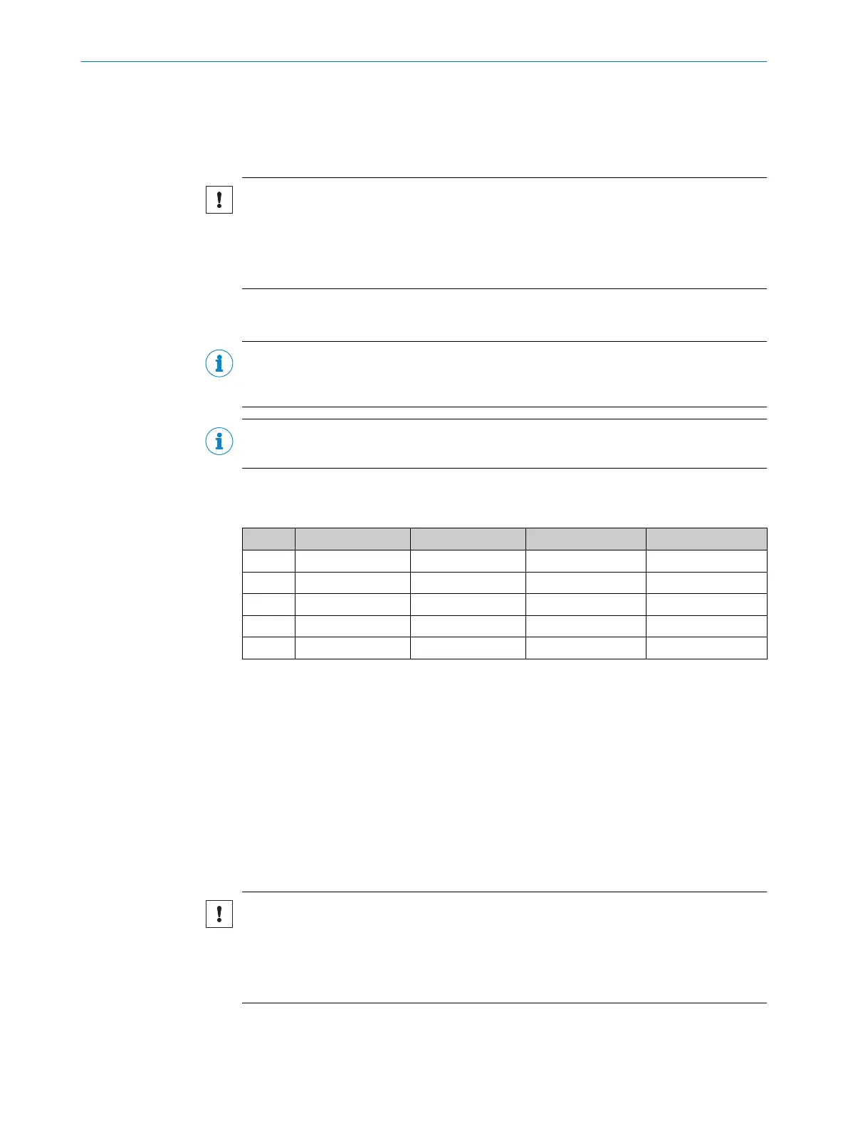
Overview of pin assignment
Table 2: M12 male connector, 5-pin
2-P 1-P dyn. AUTO
1 L+ L+ L+ L+
2 Q Q Q Q
3 M M M M
4 Q/C Q/C Q/C Q/C
5 ET ET ET L/D
Legend
L+ = supply voltage
M = ground
Q = switching output
Q/C = switching output and communication
ET = external teach-in
L/D = light/dark
5.4
Connecting the supply voltage
NOTICE
Risk of damage to the device!
The device can become damaged if it is connected to a voltage supply that is already
switched on.
•
Only connect the device when the supply cable is de-energized.
The device must be connected to a power supply unit with the following properties:
ELECTRICAL INSTALLATION 5
8020708.ZMT3/ | SICK O P E R A T I N G I N S T R U C T I O N S | KTS/KTX Prime
17
Subject to change without notice

 Loading...


