EasyManuals Logo

SICK microScan3 Core I/O AIDA Mounting Instructions

SICK microScan3 Core I/O AIDA
To Next Page IconTo Next Page
To Previous Page IconTo Previous Page
Page #13 background imageLoading...
Page #13 background image
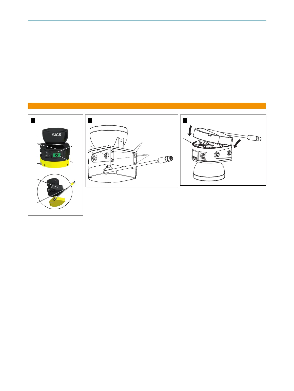
4. Unscrew screws in the defective system plug and remove the system plug from the
s
afety laser scanner.
5.
Make sure that the seal 1 is seated correctly.
6.
Carefully place the new system plug onto the safety laser scanner at the back 2.
7.
Carefully fold the system plug onto the safety laser scanner 3.
8. Screw in the system plug using the captive screws. Tightening torque: 1.6 Nm …
1.9 Nm.
9. Reconnect the connecting cables to the system plug.
10. Configure the safety laser scanner.
11. Perform commissioning again, taking particular care to conduct all of the thorough
checks described. For more information, see the operating instructions.
A
B
1
2
2
C
1
3
2
MOUNTING INSTRUCTIONS
8021255/1AM9/2021-02-19 | SICK M O U N T I N G I N S T R U C T I O N S | microScan3 Core I/O AIDA
13
Subject to change without notice

Other manuals for SICK microScan3 Core I/O AIDA

Questions and Answers:

Question and Answer IconNeed help?

Do you have a question about the SICK microScan3 Core I/O AIDA and is the answer not in the manual?

SICK microScan3 Core I/O AIDA Specifications

General IconGeneral
Scanning angle275°
Protection classIP65
Configuration methodSOPAS ET
Enclosure ratingIP65
Dimensions102 mm x 152 mm x 106 mm
Scanning range5.5 m
Protective field range5.5 m
Number of monitoring cases128
Supply voltage24 V DC
Performance levelPL e (ISO 13849-1)
Warning field range5.5 m
Resolution for safety field30 mm / 40 mm / 50 mm / 70 mm
Connection typeM12
Protective field resolution30, 40, 50, 70 mm
Number of protective fields128

Related product manuals