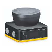
How to fix a faulty configuration on a SICK microScan3 Core I/O?
- SStephanie AllenAug 18, 2025
If the SICK Scanner has a faulty configuration, you should reconfigure the device.
How to fix a faulty configuration on a SICK microScan3 Core I/O?
If the SICK Scanner has a faulty configuration, you should reconfigure the device.
What causes an incompatible configuration in SICK microScan3 Core I/O Scanner?
An incompatible configuration in the SICK Scanner occurs when the configuration in the system plug does not match the device’s functionality. To resolve this, check the device variant, or replace/reconfigure the device.
How to fix an invalid EDM configuration on a SICK Scanner?
If the configuration of the external device monitoring (EDM) is invalid because it is unsuitable for the wiring, check whether the external device monitoring is connected correctly. Alternatively, use Safety Designer to check the configuration.
What to do if there is a fault in the reset input of SICK microScan3 Core I/O Scanner?
If an invalid signal is applied at a reset input because the reset signal is applied for too long, check the reset pushbutton, the wiring, and any other components affected.
What to do if there is a fault in the safety laser scanner SICK?
If the safety laser scanner has an internal fault, you can try performing a device restart using the display or Safety Designer, or interrupt the voltage supply for at least two seconds. If the issue persists, replace the safety laser scanner and send it to the manufacturer for repair.
Why is the firmware incompatible with my SICK Scanner?
The configuration in the system plug does not match the device’s firmware version. To solve this, check the firmware version of the device or replace/reconfigure the device.
What to do if there is a fault in the system plug of SICK Scanner?
If the system plug has an internal fault, perform a device restart using the display or Safety Designer, or interrupt the voltage supply for at least two seconds. If that doesn't work, replace the system plug.
What to do if there is a fault in the external device monitoring (EDM) of SICK microScan3 Core I/O Scanner?
If a faulty signal is applied at the external device monitoring (EDM) and the allowed tolerance time has been exceeded, check whether the connectors are wired correctly and operating correctly.
How to troubleshoot a short-circuit at the reset input in SICK microScan3 Core I/O Scanner?
If exactly the same signal is applied at a reset input as at another input, an OSSD or an output, there is possibly a short-circuit. Check the wiring for cross-circuits.
What should I do if there is a short-circuit between OSSD and universal input/output in SICK Scanner?
If there is a short-circuit between an OSSD and a universal input or between an OSSD and a universal I/O, check wiring.
Details product ordering codes and part numbers.
Explains document purpose, scope, target audience, resources, and symbols.
Covers laser safety, general precautions, and hazardous radiation warnings.
Defines proper applications, unsuitable uses, and required personnel expertise.
Explains function, device overview, characteristics, field types, and examples.
Covers manufacturer/operator duties, assembly, and mounting considerations.
Details response time, contour monitoring, protection types, system integration, and electrical requirements.
Outlines requirements for thorough checks, regular inspections, and testing notes.
Covers safety, unpacking, mounting options, and fitting the system plug.
Highlights electrical safety, requirements, connection overview, and pin assignment.
Details Safety Designer, installation, projects, general requirements, and delivery state.
Explains user interface, groups, settings, identification, and application setup.
Covers monitoring planes, reference contour fields, fields, and field editor functions.
Details local I/Os, monitoring cases, simulation, transfer, and reports.
Covers safety, alignment, switching on, and checks during commissioning and modifications.
Details operating safety, thorough checks, LEDs, and buttons/display.
Covers safety during maintenance and regular cleaning of the optics cover.
Details replacing the optics cover and the safety laser scanner.
Details safety, diagnostic LEDs, display information, and fault displays.
Covers data recorder, event history, and message history for system analysis.
Provides guidance on the proper disposal of unusable devices according to regulations.
Details variant overview, version numbers, functional scope, and features.
Lists safety parameters, interfaces, electrical, mechanical, ambient, response times, and sensing ranges.
Covers compliance with EU directives and specifies relevant standards.
Provides a commissioning checklist and mounting methods for interference protection.
| Scanning angle | 275° |
|---|---|
| Protection class | IP65 |
| Number of protective fields | Up to 128 |
| Number of warning fields | Up to 128 |
| Ambient temperature range | -10°C to +50°C |
| Storage temperature range | -25°C to +70°C |
| Number of fields | 128 |
| Number of monitoring cases | 128 |
| Interfaces | Ethernet, USB, I/O |
| Number of field sets | 128 |
| Angular resolution | 0.1 ° |
| Supply voltage | 24 V DC |
| Operating voltage | 24 V DC |
| Housing material | Aluminum |


