microScan3
Core I/O
S1
k1
k2
K1 K2 H1
+24 V DC
FE
0 V DC
E136289/
01/2015-12-01
k2k1
x
x
y
y
z
z
k2
k1
1)
+24 V DC
Uni-I/O 1
Uni-I/O 2
Uni-I/O 3
OSSD 1.A
OSSD 1.B
0 V DC
FE
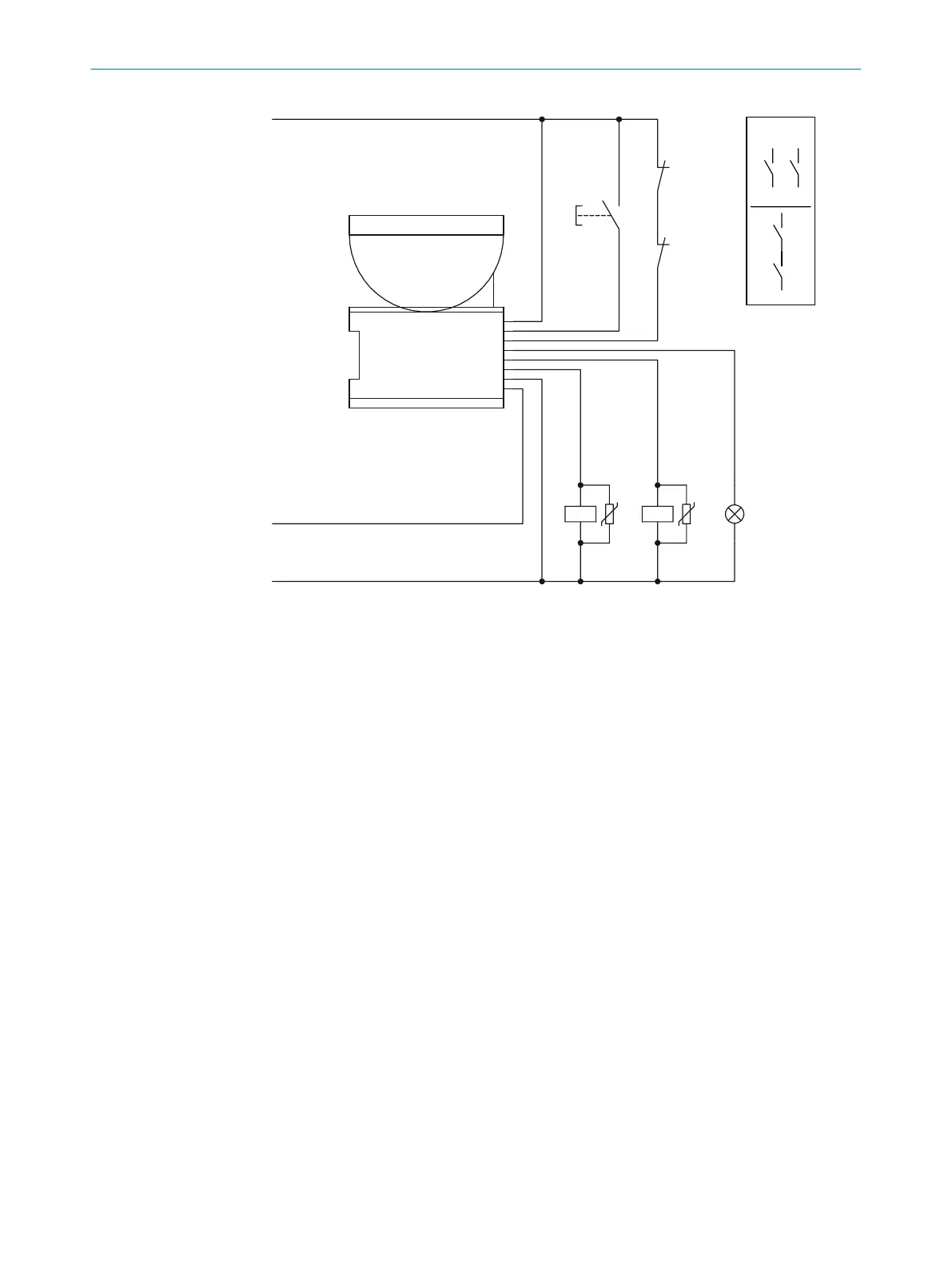
Figure 44: Connection diagram with restart interlock and external device monitoring (EDM)
Uni-I/O 1 configured as input r
eset
Uni-I/O 2 configured as input external device monitoring (EDM)
Uni-I/O 3 configured as output reset required
5.5 Testing plan
The protective device must be tested by appropriately qualified safety personnel when
commis
sioning, after modifications and at regular intervals.
The manufacturer and user must define the type and frequency of the thorough checks
of the machine on the basis of the application conditions and the risk assessment.
Determination of the thorough checks must be documented in a traceable manner.
The following tests must be planned:
•
A thorough check must be carried out during commissioning and following modifi‐
cations.
•
The regular tests of the safety laser scanner must fulfill certain minimum require‐
ments.
A test object is required for some thorough checks. An optically opaque cylinder with
a black surface can be used as a suitable test object. The diameter must match the
configured resolution.
5.5.1 Test during commissioning and in certain situations
Minimum requirements
T
he protective device and its application must be thoroughly checked in the following
situations:
•
Before commissioning
•
After changes to the configuration or the safety function
5 PROJECT PLANNING
60
O P E R A T I N G I N S T R U C T I O N S | microScan3 Core I/O 8025870/2020-09-04 | SICK
Subject to change without notice