Table 5: Status of the channels of the control inputs with complementary evaluation
A1 A2 Logical input status (input A)
1 0 0
0 1 1
1 1 Fault
0 0 Fault
In antivalent evaluation, the 2 channels of each static control input must always be
in
verted, even if the status of a control input in a monitoring case is random. If it is not
inverted, all safety outputs switch to the OFF state and the device displays a fault.
5.4.5 Universal inputs, universal outputs, universal I/Os
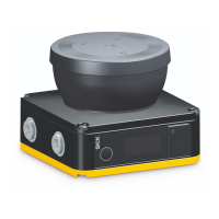
The safety laser scanner is equipped with universal I/Os.
U
niversal I/O can be configured as universal input or as universal output.
Depending on the device, a universal input can be used for resetting, external device
monitoring (EDM), sleep mode, or restarting the protective device, for example. If sleep
mode is activated by a universal input, the sleep mode must not be used for safety
applications. Certain universal inputs can also be used in pairs as a static control input.
A universal output outputs a signal depending on its configuration, e.g. if the reset
pushbutton needs to be pushed or if the optical cover is contaminated. A universal
output must not be used for safety functions.
b
Use the same earthing method for all devices that are electrically connected to the
safety laser scanner.
b
Voltage must be supplied in accordance with SELV/PELV (IEC 60204-1) for all
devices that are electrically connected to the safety laser scanner.
b
All devices that are electrically connected to the safety laser scanner must be
supplied by the same voltage supply.
Information about electrical properties: see "Technical data", page 142
Information about pin assignment: see "Electrical installation", page 69
5.4.6 Restart interlock
Depending on the regulations which apply at the place of installation, a restart interlock
ma
y be required.
The restart interlock prevents the machine from automatically starting up, for example
after a protective device has responded while the machine is operating or after chang‐
ing the machine’s operating mode.
First, the operator must press a reset pushbutton to return the protective device to
monitoring status. Then, in a second step, the operator can restart the machine.
Depending on applicable national regulations, a restart interlock must be available if it
is possible to stand behind the protective field.
Reset
T
he reset brings the protective device back to the monitoring state after it has sent
a stop command. The reset also quits the start-up or restart interlock of a protective
device, so that the machine can be restarted in a second step.
The reset must only be possible, when all safety functions and protective devices are
functional.
5 PROJECT PLANNING
56
O P E R A T I N G I N S T R U C T I O N S | microScan3 Core I/O 8025870/2020-09-04 | SICK
Subject to change without notice

 Loading...


