Table 16: Status LEDs
Number Function Color Meaning
1
OFF state Red Lights up red when the OSSD pair is
in t
he OFF state.
2
ON state Green Lights up green when the OSSD pair
is in the ON state.
3
Warning field Yellow Shines yellow if at least one warning
field is interrupted.
4
Restart interlock Yellow Setup with reset: Flashes if the
r
estart interlock has been triggered.
Configuration with automated restart
after a time: Lights up while the con‐
figured time to restart expires.
The OFF state and ON state LEDs can be found in multiple locations on the safety laser
sc
anner. 3 additional sets are arranged in pairs on the base of the optics cover. So the
LEDs can also be seen in many cases when it is not possible to see the display, e.g. due
to the mounting situation or because it is hidden from the operator’s position.
10.4 Buttons and display
The safety laser scanner is equipped with 4 pushbuttons and a graphical display. You
c
an use the buttons to show information on the display and make simple settings.
NOTE
T
he display language is set using Safety Designer during configuration. The display
language and the configuration cannot be changed using the buttons on the display.
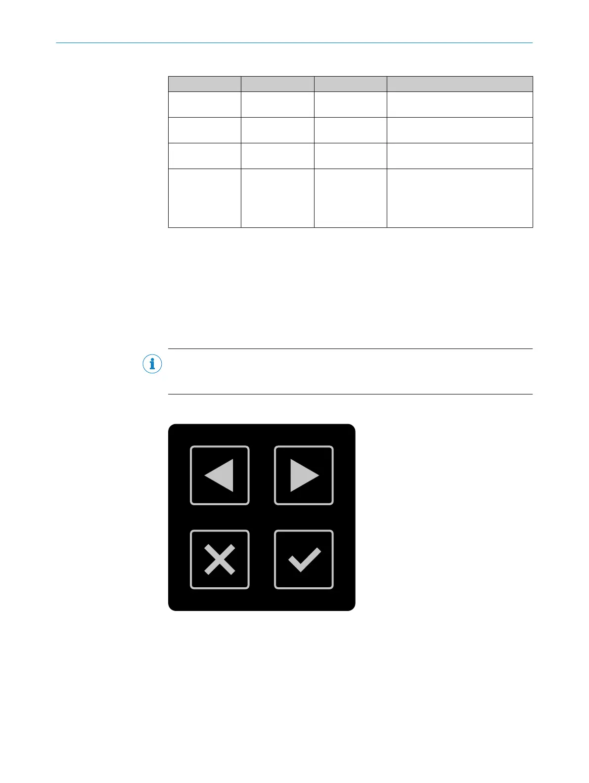
Buttons
Figure 75: Pushbuttons on the device
1, 2
You can use the arrow buttons to change between various displays and menu items.
3
You can use the back button to change to the previous display or a higher-level menu
item.
4
You can use the OK button to show details for current information or confirm a menu
point. Press the OK button twice to call up the menu.
If you do not press any pushbuttons for a time, the display changes back to the status
dis
play.
10 OPERATION
118
O P E R A T I N G I N S T R U C T I O N S | microScan3 Core I/O 8025870/2020-09-04 | SICK
Subject to change without notice