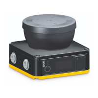
The OFF state and ON state LEDs can be found in multiple locations on the safety laser
sc
anner. 3 additional sets are arranged in pairs on the base of the optics cover. So the
LEDs can also be seen in many cases when it is not possible to see the display, e.g. due
to the mounting situation or because it is hidden from the operator’s position.
More information about the meaning of the LEDs see "Diagnostic LEDs", page 129.
Depending on the configuration, the display shows current information about the safety
laser scanner’s status, see "Buttons and display", page 118.
4.2.4 Connections
•
1 × connec
ting cable with male connector, M12, A-coded for voltage supply,
OSSDs and universal I/Os (can be used as universal input, universal output or in
pairs as static control input)
•
1 × female connector, USB 2.0 Mini-B for configuration and diagnosis
1)
OSSD
An O
SSD is a safety switching output. The functionality of each OSSD is tested periodi‐
cally. OSSDs are always connected in pairs and must undergo dual-channel analysis for
safety reasons. An OSSD pair is formed from 2 OSSDs that are connected and analyzed
together.
Control input
A control input receives signals, e.g. from the machine or from the control. Use of
control inputs is how the protective device receives information about the conditions
at the machine, e.g., if there is a change of operating mode. If the protective device
is configured appropriately, it will activate a different monitoring case after receiving a
new control input.
The control input information must be transmitted reliably. Generally, at least 2 sepa‐
rate channels are used to do this.
A static control input is a dual-channel control input, which evaluates the status of every
c
hannel as the value 0 or 1. The signal states of a static control input give a unique
signal pattern. This signal pattern activates a monitoring case.
Universal I/O
Universal I/O can be configured as universal input or as universal output.
Universal input
Depending on the device, a universal input can be used for resetting, external device
monitoring (EDM), sleep mode, or restarting the protective device, for example. If sleep
mode is activated by a universal input, the sleep mode must not be used for safety
applications. Certain universal inputs can also be used in pairs as a static control input.
Universal output
A uni
versal output outputs a signal depending on its configuration, e.g. if the reset
pushbutton needs to be pushed or if the optical cover is contaminated. A universal
output must not be used for safety functions.
4.2.5 System plug
A system plug is required to operate the safety laser scanner.
T
he base plate is the system plug (see figure 4, page 15).
1)
T
he USB connection may only be used temporarily and only for configuration and diagnostics.
PRODUCT DESCRIPTION 4
8025870/2020-09-04 | SICK O P E R A T I N G I N S T R U C T I O N S | microScan3 Core I/O
17
Subject to change without notice
 Loading...


