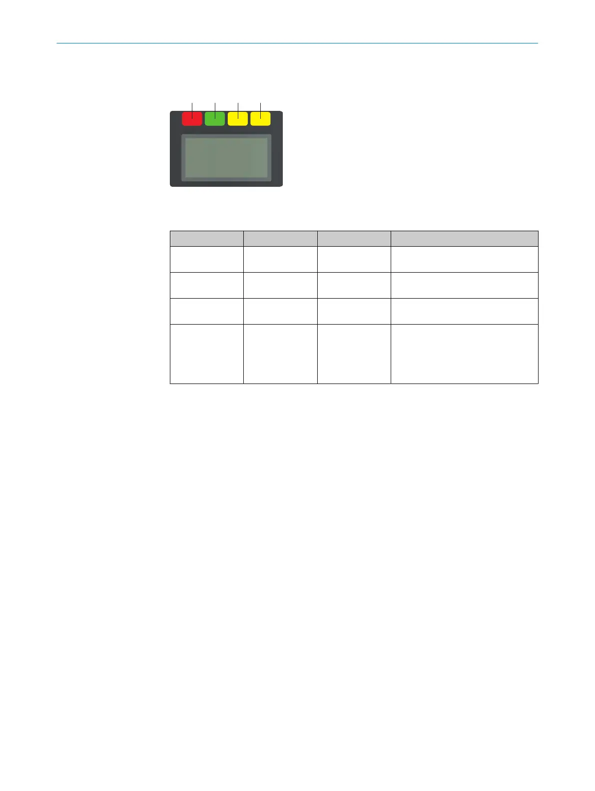
When the start procedure is complete, the status LEDs and the display show the safety
la
ser scanner’s current operational status.
Figure 72: Status LEDs
T
able 15: Status LEDs
Number Function Color Meaning
1
OFF state Red Lights up red when the OSSD pair is
in t
he OFF state.
2
ON state Green Lights up green when the OSSD pair
is in the ON state.
3
Warning field Yellow Shines yellow if at least one warning
field is interrupted.
4
Restart interlock Yellow Setup with reset: Flashes if the
r
estart interlock has been triggered.
Configuration with automated restart
after a time: Lights up while the con‐
figured time to restart expires.
The OFF state and ON state LEDs can be found in multiple locations on the safety laser
sc
anner. 3 additional sets are arranged in pairs on the base of the optics cover. So the
LEDs can also be seen in many cases when it is not possible to see the display, e.g. due
to the mounting situation or because it is hidden from the operator’s position.
More information about what the LEDs mean and the symbols and information shown
on the display: see "Troubleshooting", page 129.
9.4 Check during commissioning and modifications
The test is intended to ensure that the hazardous area is monitored by the protective
de
vice and that unprotected access to the hazardous area is prevented.
b
C
arry out the checks according to the instructions from the manufacturer of the
machine and from the operating entity.
9 C
OMMISSIONING
116
O P E R A T I N G I N S T R U C T I O N S | microScan3 Core I/O 8025870/2020-09-04 | SICK
Subject to change without notice