4.2 Product characteristics
4.2.1 Device overview
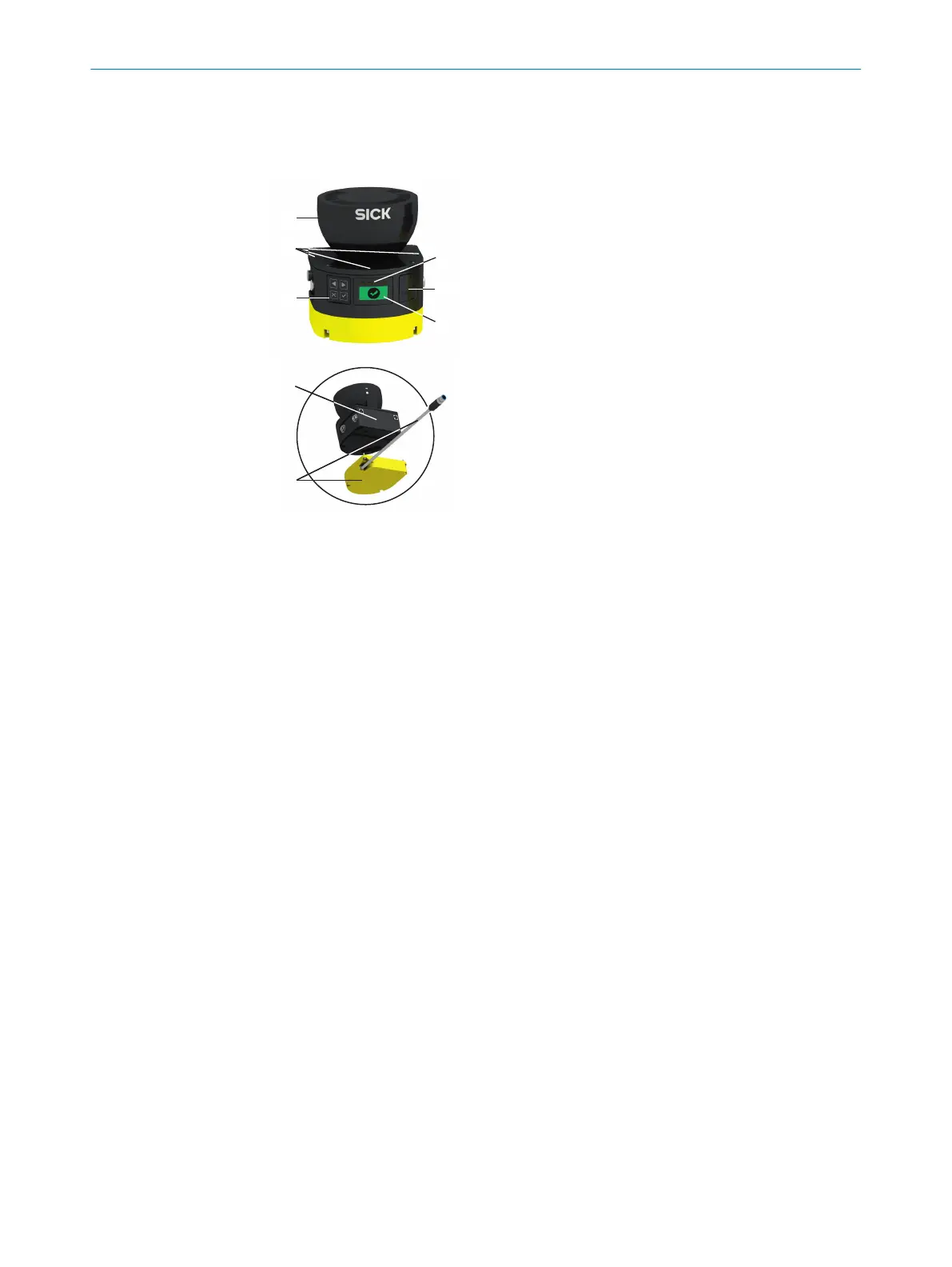
Figure 4: Device overview
1
Optics cover
2
Display
3
Keypad
4
USB connection
5
Status LEDs
6
Additional LEDs for ON state and OFF state
7
Safety laser scanner without system plug
8
System plug
Different variants of the safety laser scanner are available, see "V
ariants", page 16.
Further information about the variants see "Variant overview", page 142.
All variants have an optics cover and the rotating mirror is located below the optics
cover. The light pulses are emitted and the reflected light pulses are received through
the optics cover.
The display with 4 pushbuttons is located below the optics cover. The safety laser
scanner also has a number of LEDs, see "Status indicators", page 16, see "Buttons
and display", page 118.
Information about connections: see "Connections", page 17.
The safety laser scanner can be mounted and operated in any alignment. In this
document, position and direction information is used as follows with respect to the
safety laser scanner, as long as different usage is not indicated separately:
•
The top is the side of the safety laser scanner on which the optics cover is located.
•
The bottom is the side of the safety laser scanner opposite the optics cover.
•
The front is the side of the safety laser scanner on which the display is located.
The 90° angle of the sector of a circle scanned by the safety laser scanner points
in this direction.
•
The back is the side of the safety laser scanner opposite the display. The sector of
a circle not scanned by the safety laser scanner lies in this direction.
PRODUCT DESCRIPTION 4
8025870/2020-09-04 | SICK O P E R A T I N G I N S T R U C T I O N S | microScan3 Core I/O
15
Subject to change without notice