7.2.1 microScan3 Core
Table 6: System plug and connections: microScan3 Core
Safety laser scanner Suitable system plug Plug connector
microScan3 Core I/O
MICSX-ABIZZZZZ3 (part number: 2118085)
•
C
onnecting cable with M12 plug
connector, see page 71
7.3 Pin assignment
You will find the pin assignment for the individual plug connectors in the following.
7.3.1 Connecting cable with M12 plug connector
Voltage is supplied and local inputs and outputs are connected via the connecting
c
able with an 8-pin, A-coded M12 male connector.
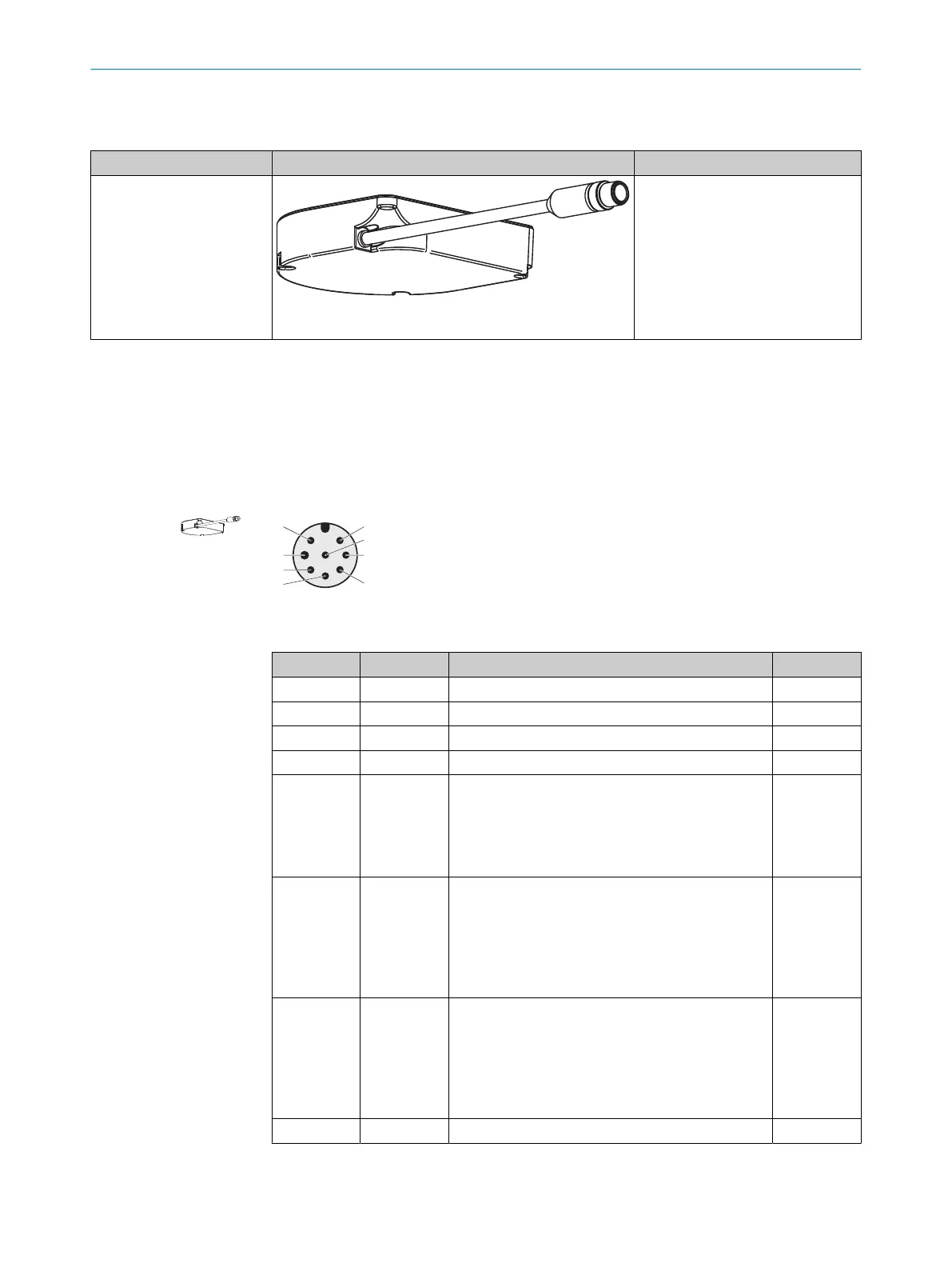
Figure 51: Pin assignment of the connecting cable (male connector, M12, 8-pin, A-coded)
Table 7: Pin assignment of the connecting cable with M12 plug connector
Pin Marking Function Wire color
1)
1 +24 V DC Supply voltage (+24 V DC) Brown
2 OSSD 1.A OSSD pair 1, OSSD A White
3 0 V DC Supply voltage (0 V DC) Blue
4 OSSD 1.B OSSD pair 1, OSSD B Black
5 Uni-I/O 1 Universal I/O 1, configurable:
•
U
niversal input: resetting, EDM (external device
monitoring), sleep mode, restarting the device
•
Universal output: contamination, fault, reset
required, monitoring result (warning field)
Gray
6 Uni-I/O 2 Universal I/O 2, configurable:
•
C
ontrol input A1 (together with pin 7)
•
Universal input: resetting, EDM (external device
monitoring), sleep mode, restarting the device
•
Universal output: contamination, fault, reset
required, monitoring result (warning field)
Pink
7 Uni-I/O 3 Universal I/O 3, configurable:
•
C
ontrol input A2 (together with pin 6)
•
Universal input: resetting, EDM (external device
monitoring), sleep mode, restarting the device
•
Universal output: contamination, fault, reset
required, monitoring result (warning field)
Violet
8 FE Functional earth/shield Orange
1)
Applies to the extension cables recommended as accessories.
ELECTRICAL INSTALLATION 7
8025870/2020-09-04 | SICK O P E R A T I N G I N S T R U C T I O N S | microScan3 Core I/O
71
Subject to change without notice