Draw rectangle
Draw circle
Draw circle segment
Mask areas (see "Dr
awing in points that cannot be monitored",
page 98). Use the drawing functions for fields to draw the masked
areas. The buttons are crosshatched.
Enable propose field
Edit a field using coordinates (see "E
diting fields using coordinates",
page 97)
Push the object into the foreground or background
Select field design
Calculate field
Zoom in
Zoom out
Zoom to area
Zoom to work space
Show snapshot of the spatial contour. Clicking again clears the spatial
cont
our shown.
Show live spatial contour
Paste background image (see "Bac
kground image", page 95)
Open field editor settings
Field display
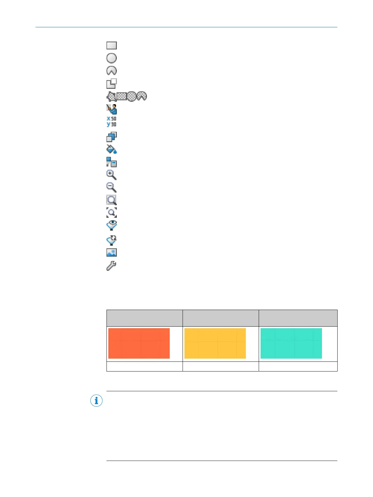
S
afety Designer displays the field types in different colors.
Table 11: Colors of the field types
Protective field Warning field Reference contour field and
c
ontour detection field
Red Yellow Turquoise
Create fields and field sets
NOTE
Y
ou can only create the number of fields and field sets allowed in the safety laser
scanner’s performance package. If the maximum number of fields and field sets has
already been used, it is not possible to create any more fields or field sets.
Create the fields in a field set in the same order that you need them in the monitoring
case table (see "Cut-off paths", page 107).
If you choose, e.g., protective field, warning field, the protective field acts on cut-off path
1 and the warning field acts on cut-off path 2.
8 C
ONFIGURATION
92
O P E R A T I N G I N S T R U C T I O N S | microScan3 Core I/O 8025870/2020-09-04 | SICK
Subject to change without notice