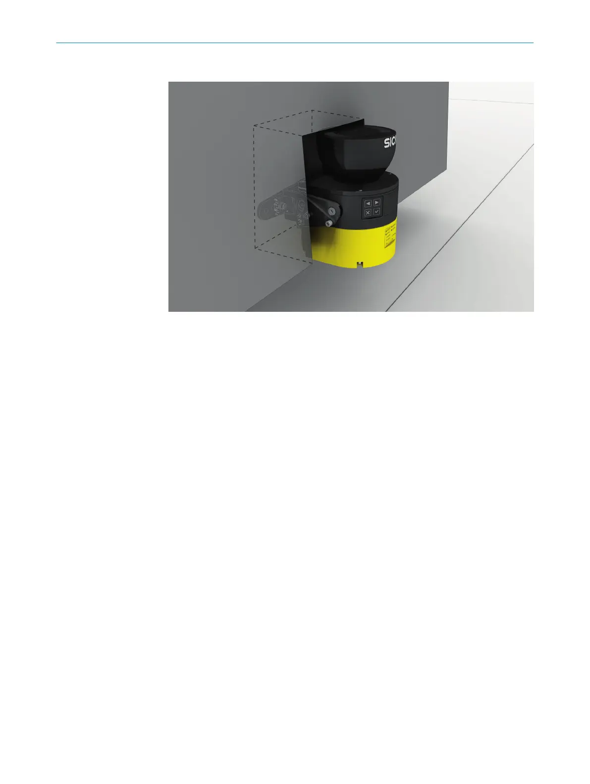
Mounting in the machine or vehicle’s paneling
Figure 21: Mounting in vehicle paneling (example)
b
If a v
iewing slit is required, make sure that its size is sufficient, see "Dimensional
drawings", page 152.
5.3.3 Response time of the safety laser scanner
The safety laser scanner’s response time must be taken into account, among other
t
hings, so that the safety laser scanner can be positioned in a suitable location and the
protective fields can be sized correctly.
The response times are specified in the technical data, see "Response times",
page 147.
The response time of the safety laser scanner resulting from current settings is shown
in Safety Designer.
5.3.4 Reference contour monitoring
Reference contour field
T
he reference contour field monitors a contour of the environment. The safety laser
scanner switches all safety outputs to the OFF state if a contour does not match the set
parameters, because, for example, the mounting situation of the safety laser scanner
were changed.
National and international standards require or recommend that a reference contour is
monitored, if the safety laser scanner is used in vertical operation for hazardous point
protection or for access protection.
The reference contour field detects unintentional and intentional changes to the posi‐
tion or alignment of the safety laser scanner. Unintentional changes may be caused by
vibrations for example. An example of an intentional change is deliberate tampering to
disable the safety laser scanner’s functionality.
Vertical operation
N
ational and international standards require or recommend that a reference contour is
monitored, if the angle between access direction and scan plane exceeds +30°.
5 P
ROJECT PLANNING
30
O P E R A T I N G I N S T R U C T I O N S | microScan3 Core I/O 8025870/2020-09-04 | SICK
Subject to change without notice