NOTE
In some c
ases, it is not possible to define when to switch (for example because
processing times of the machine vary) or the time advance means that the monitoring
of an area finishes too early. Follow one of the following recommendations in these
cases:
b
Allow the two protective fields to partially overlap.
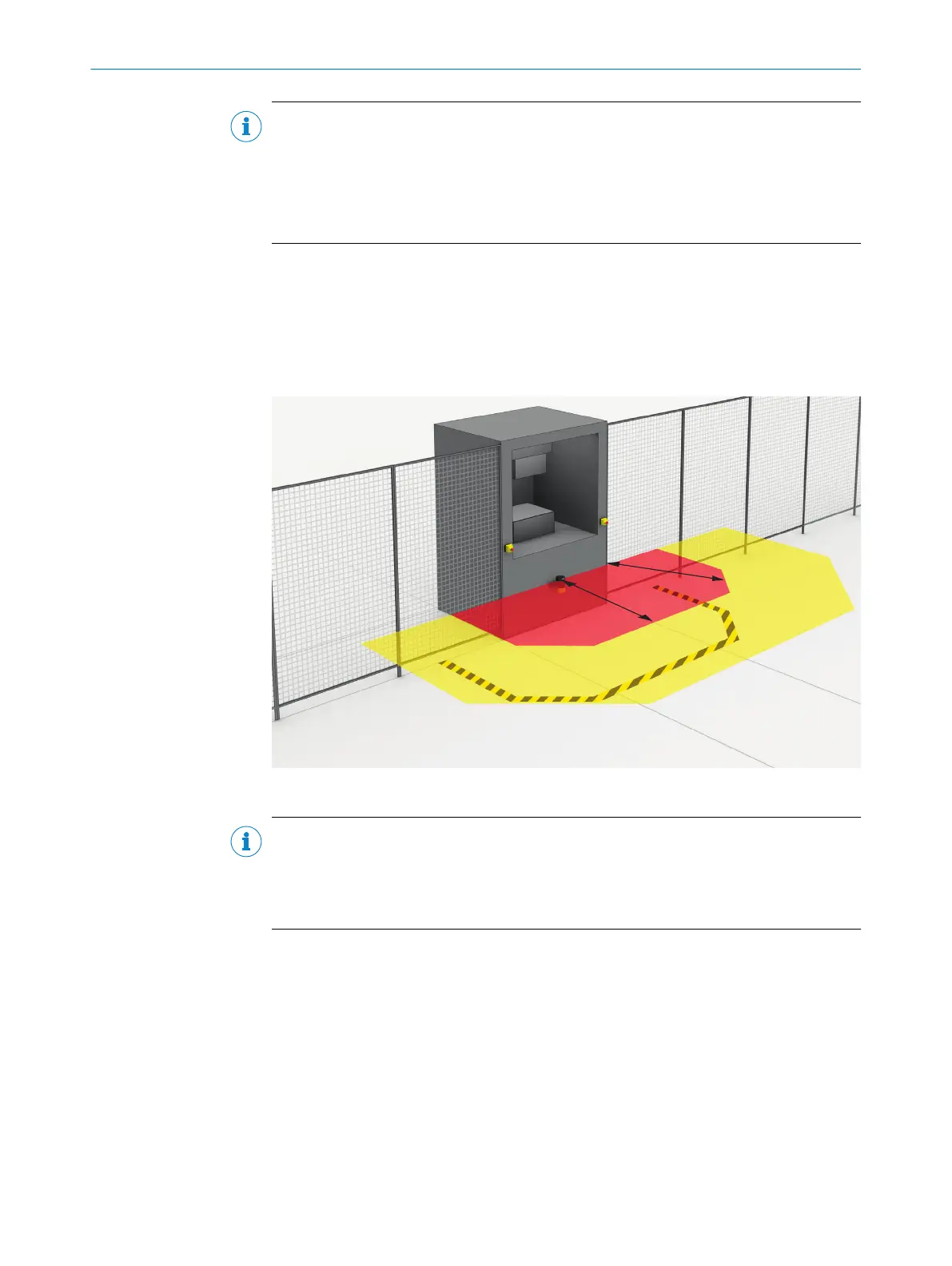
5.3.6 Hazardous area protection
The safety laser scanner is mounted with a horizontal scan plane in a stationary
applic
ation, for example on a machine where the hazardous area is not completely
surrounded by a physical guard. During hazardous area protection, the safety laser
scanner detects a person’s legs. The protective field is parallel to the person’s direction
of approach.
Figure 24: Stationary application with horizontal scan plane for hazardous area protection
NOTE
Mar
k the outline of the protective field boundaries on the floor after you have worked
out the protective field size. By doing this, you allow machine operators to see the pro‐
tective field boundaries and make it easier to thoroughly check the protective function
at a later date.
5.3.6.1 Protective field
Overview
T
he protective field must be designed so that it detects a person at a minimum
distance from the hazardous point. This distance is required to prevent a person or
part of their body from reaching the hazardous area before the end of the machine’s
dangerous state.
In hazardous area protection, the minimum distance typically defines the protective
field size required.
If you define a number of monitoring cases with different protective fields, you must
calculate the protective field size separately for each protective field used.
5 P
ROJECT PLANNING
34
O P E R A T I N G I N S T R U C T I O N S | microScan3 Core I/O 8025870/2020-09-04 | SICK
Subject to change without notice