Figure 10: RFH505 and RFH510: Required protrusion of the active cap (blue) when mounting the
device in metal (non-flush installation)
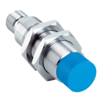
RFH515
Figure 11: RFH515/515: recommended overrun of the active head when mounting the device in
metal: about 10mm (non-flush installation)
Figure 12: RFH515: recommended overrun of the active head when mounting the device on
metal: about 10mm
Basic allocation of the transponder to the device
HF transponders have coil antennas and therefore preferential directions within the
radiation field of the antenna. The possible read and write range is lower or higher
depending on the alignment of the transponder antenna to the antenna surface of the
device.
MOUNTING 5
8025309/1KDE/2023-12-19 | SICK O P E R A T I N G I N S T R U C T I O N S | RFH5xx
25
Subject to change without notice
 Loading...