Pin assignment of the connecting cable with M12 plug connector, 8-pin
PIN Designation Function
1 +24 V DC Supply voltage (+24 V DC)
2 OSSD1 OSSD1 (switching output 1)
3 0 V DC Supply voltage (0 V DC)
4 OSSD2 OSSD2 (output signal switching device 2)
5 Uni-O Universal output, configurable: Monitoring result, conta‐
mina
tion, error
6 IN 1 Control input 1: Monitoring case switching
7 IN 2 Control input 2: Monitoring case switching
8 IN 3 Control input 3: Monitoring case switching
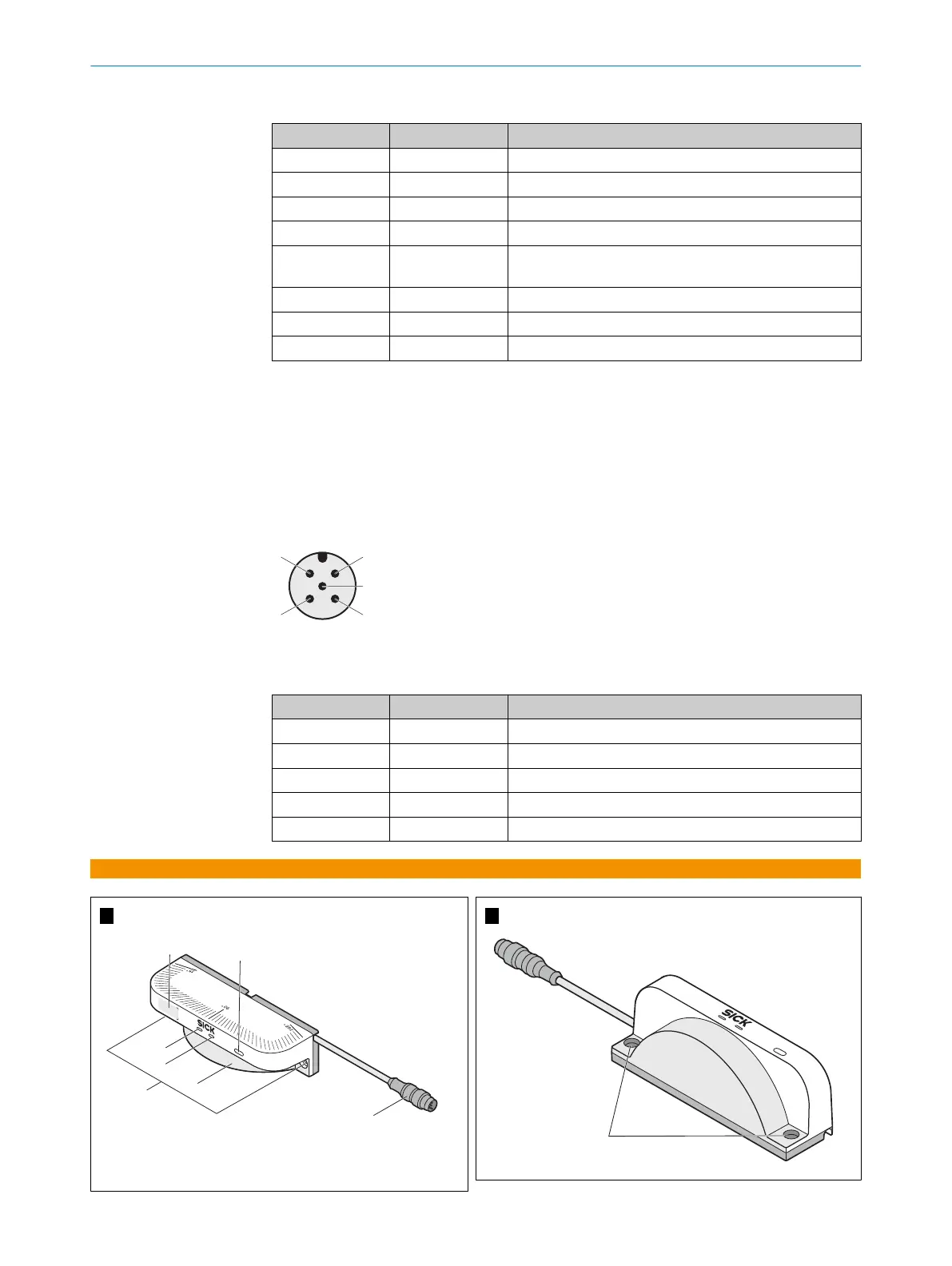
6.2 Pin assignment of scanGrid2 CANopen
Connecting cable with M12 plug connector, 5-pin
V
oltage supply and local inputs and outputs
•
Male connector
•
M12
•
5-pin
•
A-coded
Figure 2: Connecting cable (male connector, M12, 5-pin, A-coded)
P
in assignment of the connecting cable with M12 plug connector, 5-pin
PIN Designation Function
1 CAN shield Shielding
2 +24 V DC Supply voltage (+24 V DC)
3 0 V DC Supply voltage (0 V DC)
4 CAN HIGH CAN signal
5 CAN LOW CAN signal
A
B
MOUNTING INSTRUCTIONS
8025966/2020-12-02 | SICK M O U N T I N G I N S T R U C T I O N S | scanGrid2 I/O, scanGrid2 CANopen
9
Subject to change without notice
 Loading...


