3. Minimum depth of thread: 12 mm.
4.
Tightening torque: 4.5 Nm … 5.0 Nm.
5 Replacing the device
Important information
DANGER
H
azard due to lack of effectiveness of the protective device
If an unsuitable configuration has been saved, it may cause the dangerous state to not
end in time.
b
Make sure that the configuration is restored after replacing the device.
b
Make sure that the safe multibeam scanner is aligned correctly after replacing the
device.
Approach
1.
Disconnect the connecting cables to the safe multibeam scanner.
2. Unscrew the fixing screws and remove the defective safe multibeam scanner.
3. Mount the new safe multibeam scanner.
4. Reconnect the connecting cables to the new safe multibeam scanner.
5. Configure the safe multibeam scanner.
NOTE
Y
ou can use the Safety Assistant app to copy the verified configuration of a device
and transfer it to a new device.
6. Perform commissioning again, taking particular care to conduct all of the thorough
c
hecks described.
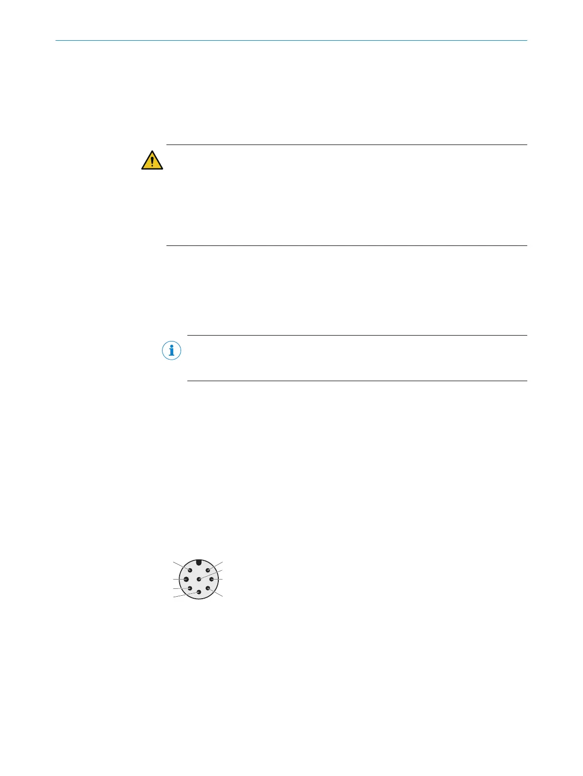
6 Pin assignment
6.1 Pin assignment of scanGrid2 I/O
Connecting cable with M12 plug connector, 8-pin
V
oltage supply and local inputs and outputs
•
Male connector
•
M12
•
8-pin
•
A-coded
Figure 1: Connecting cable (male connector, M12, 8-pin, A-coded)
MOUNTING INSTRUCTIONS
8
M O U N T I N G I N S T R U C T I O N S | scanGrid2 I/O, scanGrid2 CANopen 8025966/2020-12-02 | SICK
Subject to change without notice
 Loading...


