English
A
Dimensions / Abmessungen
All dimensions in mm (inch)
Alle Maße in mm (inch)
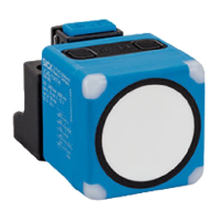
1 Control elements / Bedienelemente
2
1
D1
2
1
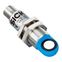
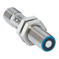
UC30-215
All types /
Alle Typen
M12x1
47 (1
.85
)
2.45
7.6
(0.3)47 (
1.85)
52
(2.05)
8.1
(0.32)
5.2
(0.2)
8.5
(0.33)
11 (
0.43
)
36.7 (
1.44
)
31.1 (1.22)31.1 (1.22)
7.6
(
0.3)
7.6
(
0.3)
7.6
(0.3)
47 (1
.85
)
7.6
(
0.3)47 (1.85)
M12x1
34
(1.34)
8.1
(0.32)
5.2
(0.2)
8.5
(0.33)
11 (
0.43
)
32.7 (
1.29
)
31.1 (1.22)
31.1 (1.22)
7.6
(
0.3)
7.6
(
0.3)
7.6
(0.3)
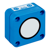
T1 T2
D2
Deutsch
Subject to change without notice
Irrtümer und Änderungen vorbehalten
8017711/1HH5/2022-10
UC30-21_163
Ultraschallsensor UC30-2
Mit Analogausgang
Betriebsanleitung
Sicherheitshinweise
•
Vor der Inbetriebnahme die Betriebsanleitung lesen.
•
Anschluss, Montage und Einstellung nur durch Fachper-
sonal.
•
Gerät bei Inbetriebnahme vor Feuchte und Verunreini-
gung schützen.
•
Das Gerät ist kein Sicherheitsbauteil im Sinne der jeweils
gültigen Sicherheitsnormen für Maschinen.
Bestimmungsgemäße Verwendung
Die Sensoren UC30-21_163 sind Ultraschallsensoren und
werden zum berührungslosen Erfassen von Sachen, Tieren
und Personen eingesetzt.
Hinweise
•
Unterhalb der Betriebsreichweite des Ultraschallsensors
UC30-2 ist keine Entfernungsmessung möglich.
•
Die UC30-2 Sensoren verfügen über eine interne Tempe-
raturkompensation. Aufgrund der Eigenerwärmung des
Sensors erreicht die Temperaturkompensation nach ca.
30 Minuten Betriebszeit ihren optimalen Arbeitspunkt.
•
Die automatische Erkennung der Last am Analogausgang
erfolgt während des Einschaltens der Versorgungsspan-
nung. Daraufhin schaltet sich der Sensor automatisch in
den benötigten Modus (analoger Strom- oder Spannungs-
ausgang).
•
Analogausgang: Eine grün leuchtende LED D1 signali-
siert, dass sich ein Objekt im Bereich der Skalierung be-
ndet.
•
Der Betrieb mit der Filtereinstellung F00 (einstellbar über
Connect+ Software) ist nicht zulässig, da in diesem Fall
EMV-Störungen auftreten können.
•
Über den Connect+ Adapter (CPA) und die Connect+ Soft-
ware können Sie alle Teach-in und weitere Sensorpa-
rametereinstellungen vornehmen. Artikelnummer Con-
nect+ Adapter und Connect+ Software: 6037782.
Inbetriebnahme
Siehe Ablaufdiagramme G bis I, Seite 2.
Analogausgang
•
Skalierung einlernen (4 mA … 20 mA oder 0 V … 10 V):
Wenn zuerst die sensorferne Skalierungsgrenze und da-
nach die sensornahe Skalierungsgrenze eingelernt wird,
werden die Skalierungsgrenzen intern getauscht.
Wenn die Skalierung < 1 mm eingelernt wird, blinken bei-
de LEDs für 3 Sekunden gleichzeitig schnell als Fehleran-
zeige. Die alten Skalierungsgrenzen bleiben erhalten.
Tabelle Montageabstände ohne Einsatz von
Synchronisations- oder Multiplexbetrieb
Parallel Gegenüberliegend
UC30-214x > 2.0 m > 18 m
UC30-215x > 4.0 m > 30 m
Wenn Sie mehrere Ultraschallsensoren betreiben und der in
der oben stehenden Tabelle angegebene Montageabstand
unterschritten wird, empfehlen wir den integrierten Synchro-
nisations- oder Multiplexbetrieb zu nutzen.
Synchronisations- und Multiplexbetrieb
Synchronisations- und Multiplexbetrieb vermeiden eine
gegenseitige Beeinussung mehrerer miteinander verschal-
teter Sensoren. Der Detektionsbereich vergrößert sich auf
die Fläche, die alle via PIN 5 (MF) miteinander verschalteten
Sensoren abdecken.
Beim UC30 können max. 50 Sensoren miteinander verschal-
tet werden.
—
Im Synchronisationsbetrieb senden und empfangen alle
Sensoren die Ultraschallimpulse gleichzeitig. Der Syn-
chronisationsbetrieb beginnt automatisch, sobald die
Sensoren miteinander via PIN 5 (MF) verschaltet werden.
—
Im Multiplexbetrieb senden und empfangen alle Sen-
soren ihre Ultraschallimpulse nacheinander in einer
denierten Reihenfolge. Dies ermöglicht eine zusätzliche
Positionsbestimmung der erfassten Objekte. Um in den
Multiplexbetrieb zu wechseln, müssen den via PIN 5 (MF)
verschalteten Sensoren mittels der Software Connect+
unterschiedliche Adressen zugeordnet werden.
Wartung
SICK-Sensoren sind wartungsfrei. Abhängig vom Einsatzort
können für das Gerät in regelmäßigen Zeitintervallen folgen-
de, vorbeugende Instandhaltungsarbeiten erforderlich sein:
– Die Grenzächen vorsichtig mit Wasser reinigen.
– Verschraubungen und Steckverbindungen prüfen.
L+
1
4
brn
blk
2
wht
3
M
blu
5
Sync/
gra
nc
Q
A
1 Not connected /
Nicht belegt
2 Synchronization and
multiplex operation,
Communication Connect+ /
Synchronisations- und
Multiplexbetrieb,
Kommunikation Connect+
B
Electrical connection / Elektrischer Anschluss
4
5
3
2 1
E
2,400
(94.49)
3,600
(141.73)
3,600
(141.73)
2,400
(94.49)
1,200
(47.24)
1,200
(47.24)
0
Detection area / Erfassungsbereich in mm (inch)
3
4
5
2
0
1,200
(47.24)
3,600
2,400
(94.49)
4,800
6,000
8,400
7,200
Detection area / Erfassungsbereich in mm (inch)
1
1,600
(63.00)
2,400
(94.49)
2,400
(94.49)
1,600
(63.00)
800
(31.50)
800
(31.50)
0
Detection area / Erfassungsbereich in mm (inch)
3
4
5
2
0
800
(31.50)
2,400
(94.49)
1,600
(63.00)
3,200
4,000
5,600
4,800
Detection area / Erfassungsbereich in mm (inch)
1
Detection areas / Erfassungsbereiche
1
Detection area depending on reexion properties, size and alignment of the object /
Erfassungsbereich abhängig von Reexionseigenschaften, Größe und Ausrichtung des Objekts
2
Limiting range / Grenzreichweite
3
Operating range / Betriebsreichweite
4
Example object: Aligned plate 500 mm x 500 mm /
Beispielobjekt: Ausgerichtete Platte 500 mm x 500 mm
5
Example object: Pipe with diameter 27 mm /
Beispielobjekt: Rundstab mit Durchmesser 27 mm
Ultrasonic sensor UC30-2
With analog output
Operating Instructions
Safety notes
•
Read the Operating Instructions before commissioning.
•
Connection, mounting and setting must be performed by
qualied personnel.
•
Protect devices from moisture and contamination during
commissioning.
•
The device does not constitute a safety component in ac-
cordance with the respective applicable safety standards
for machines.
Intended use
The UC30-21_163 are ultrasonic sensors used for contact-
free detecting of objects, animals and persons.
Notes
•
Distance measurement is not possible outside of the op-
erating range of ultrasonic sensor UC30-2.
•
The UC30-2 sensors are equipped with an internal tem-
perature compensation. Due to the sensor‘s heating up,
the temperature compensation will reach its best working
point after approx. 30 minutes.
•
The load is automatically detected on the analog out-
put when the supply voltage is being switched on. At this
point, the sensor automatically switches to the mode re-
quired (analog current or voltage output).
•
Analog output: A green LED D1 signals that there is an
object in the scale area.
•
Operation with lter setting F00 (adjustable via Con-
nect+ Software) is not permitted, as EMC interference
may occur in this case.
•
The Connect+ adapter (CPA) and the Connect+ Software
can be used to perform any teach-in and other sensor
parameter settings. Part number Connect+ adapter and
Connect+ Software: 6037782.
Commissioning
See process diagrams G to I, Page 2.
Analog output
•
Teach-in scaling (4 mA … 20 mA or 0 V … 10 V):
When the sensor-far scaling limit is taught in before the
sensor-near scaling limit, the scaling limits are exchanged
internally.
When a scaling of less than 1 mm is taught in, both LEDs
will ash quickly together for 3 seconds to indicate an er-
ror. The old scaling limits are retained.
D
0 V/4 mA
10 V/20 mA
Measurement value within the scaling of the analog output → LED D1 = green
Measurement value outside of the scaling of the analog output → LED D1 = red /
Messwert innerhalb der Skalierung des Analogausgangs
→ LED D1 = grün
Messwert außerhalb der Skalierung des Analogausgangs → LED D1 = rot
Near limit /
Nahe Grenze
Far limit /
Ferne Grenze
10 V/20 mA
0 V/4 mA
D1 lights red/
D1 leuchtet rot
D1
T1 T2
D2
D1 lights green/
D1 leuchtet grün
D1
T1 T2
D2
D1 lights red/
D1 leuchtet rot
D1
T1 T2
D2
Behavior analog output and status LED /
Verhalten Analogausgang und Status-LED
C
Alignment / Ausrichtung
1 Smooth object surfaces / Glatte Objektoberächen
2 Rough object surfaces/ Raue Objektoberächen
Table assembly distances without use of
synchronization or multiplex operation
Parallel Opposite
UC30-214x > 2.0 m > 18 m
UC30-215x > 4.0 m > 30 m
If you operate several ultrasonic sensors and the assembly
distance indicated in the table "Assembly distances" is un-
dercut, we recommend using the integrated synchronization
or multiplex operation.
Synchronization and multiplex mode
Synchronization and multiplex mode prevents mutual
interference of several interconnected sensors. The detec-
tion zone increases to the area covered by all synchronized
sensors via PIN 5 (MF). A maximum of 50 sensors can be
interconnected with the UC30
—
In synchronization mode, all sensors send and receive
the ultrasonic pulses simultaneously. Synchronization
mode begins automatically as soon as the sensors are in-
terconnected via PIN 5 (MF).
—
In multiplex mode, all sensors send and receive their ul-
trasonic pulses one after another in a dened sequence.
This enables additional position detection of the recorded
objects.
To change to multiplex mode, dierent addresses must
be assigned to the sensors interconnected via PIN 5 (MF)
using the Connect+ software.
Maintenance
SICK sensors are maintenance-free. Depending on the
assignment location, the following preventive maintenance
tasks may be required for the device at regular intervals:
– Clean the optical surfaces carefully with water.
– Check screw and plug connections.
www.sick.com/UC30
- For use in NFPA79 applications only.
- UL-Listed adapters providing field wiring leads
are available.
- Refer to the product information.
BZ int49
Detailed addresses and further locations at www.sick.com
Australia
Phone +61 (3) 9457 0600
1800 33 48 02 – tollfree
Austria
Phone +43 (0) 2236 62288-0
Belgium/Luxembourg
Phone +32 (0) 2 466 55 66
Brazil
Phone +55 11 3215-4900
Canada
Phone +1 905.771.1444
Czech Republic
Phone +420 234 719 500
Chile
Phone +56 (2) 2274 7430
China
Phone +86 20 2882 3600
Denmark
Phone +45 45 82 64 00
Finland
Phone +358-9-25 15 800
France
Phone +33 1 64 62 35 00
Germany
Phone +49 (0) 2 11 53 010
Greece
Phone +30 210 6825100
Hong Kong
Phone +852 2153 6300
Hungary
Phone +36 1 371 2680
India
Phone +91-22-6119 8900
Israel
Phone +972 97110 11
Italy
Phone +39 02 27 43 41
Japan
Phone +81 3 5309 2112
Malaysia
Phone +603-8080 7425
Mexico
Phone +52 (472) 748 9451
Netherlands
Phone +31 (0) 30 229 25 44
New Zealand
Phone +64 9 415 0459
0800 222 278 – tollfree
Norway
Phone +47 67 81 50 00
Poland
Phone +48 22 539 41 00
Romania
Phone +40 356-17 11 20
Russia
Phone +7 495 283 09 90
Singapore
Phone +65 6744 3732
Slovakia
Phone +421 482 901 201
Slovenia
Phone +386 591 78849
South Africa
Phone +27 10 060 0550
South Korea
Phone +82 2 786 6321/4
Spain
Phone +34 93 480 31 00
Sweden
Phone +46 10 110 10 00
Switzerland
Phone +41 41 619 29 39
Taiwan
Phone +886-2-2375-6288
Thailand
Phone +66 2 645 0009
Turkey
Phone +90 (216) 528 50 00
United Arab Emirates
Phone +971 (0) 4 88 65 878
United Kingdom
Phone +44 (0)17278 31121
USA
Phone +1 800.325.7425
Vietnam
Phone +65 6744 3732