Do you have a question about the SICK UC40 and is the answer not in the manual?
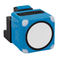
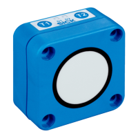
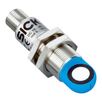
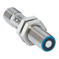
Defines the proper application of the UC40 ultrasonic sensor for non-contact detection and distance measurement.
Outlines prohibited uses, such as in hazardous areas or with unapproved accessories, and warns of potential dangers.
Specifies the necessary qualifications for mounting, electrical installation, commissioning, and operation of the device.
Highlights the importance of observing safety notes and warnings to mitigate health risks and avoid dangerous situations.
Warns about severe injury or death from electrical voltage and mandates work by qualified electricians.
Alerts to risks of injury and damage from improper grounding, emphasizing equipotential bonding.
Provides guidance on connecting cables, emphasizing de-energized states and supply voltage specifications.
Outlines essential safety requirements, including proper grounding, equipotential bonding, and qualified personnel for electrical work.
Details the pin assignment for the UC40 sensor's M12 connector, differentiating between UC40-xxxxxB and UC40-xxxxxH models.
Explains how to perform teach-in procedures using the device's pushbuttons for various output configurations.
Guides on teaching a single switching point for digital output 1 based on object distance.
Explains teaching a switching window for digital output 1, defining active output within a range.
Describes teaching a background reference for Window Mode, establishing thresholds for digital output activation.
Explains the process for teaching analog output characteristics and scaling for UC40-xxxxxH models.
Details how to select the output type (analog/digital) for pin 2 on UC40-xxxxxH models using the multifunctional input.
Explains teaching procedures for digital output 1 using the multifunctional input.
| Brand | SICK |
|---|---|
| Model | UC40 |
| Category | Accessories |
| Language | English |