7 Operation
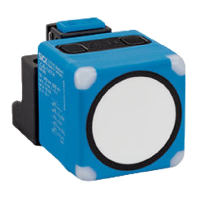
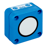
7.1 Display and control elements
Overview
1
LED 1
2
LED 2
3
LED 3
4
LED 4
5
T1 pushbutton
6
T2 pushbutton
Status LEDs
Status LED Color Status
1 Orange Pin 2 output status:
Operating mode of analog output: on = object outside
analog scaling; off = object within analog scaling
Digital output operating mode 2: on = active; off = deac‐
tivated
2 Green Output 2 operating mode:
On = analog output; off = digital output 2
3 Orange Pin 4 output status:
Digital output 1: on = active; off = deactivated
4 Green Status indicator:
On = normal operation; flashing = IO-Link operation
7.2 Note for teach-in
If a teach-in process is not complete, any changes made are discarded after 30 sec‐
onds.
7.3 Teach-in via pushbuttons
7.3.1 Setting pin 2 output (UC40-xxxxxH only)
Overview
The UC40-xxxxxH product type has a second output. For this output, it is possible to
choose between automatic current or voltage output and fixed current, voltage or digital
output. The desired output must be selected before the teach-in process.
With automatic selection of current or voltage output (factory setting), the device
checks the load at the analog output. Depending on the load, the device automatically
selects current or voltage output.
OPERATION 7
8027772//2022-08-11 | SICK O P E R A T I N G I N S T R U C T I O N S | UC40
21
Subject to change without notice