2 Mount the sensor using a suitable mounting bracket (see the SICK range of acces‐
sories).
Note the sensor's maximum permissible tightening torque of 1.3 Nm.
Note the preferred direction of the object relative to the sensor [see A].
3 The sensors must be connected in a voltage-free state (U
v
= 0 V). The information
in the graphics [B] must be observed, depending on the connection type:
– Male connector connection: pin assignment
– Cable: core color
Only apply voltage/switch on the power supply (U
v
> 0 V) once all electrical connec‐
tions have been established. The green LED indicator lights up on the sensor.
Explanations of the connection diagram (Graphic B):
Switching outputs Q and /Q (according to Graphic B):
WT(F)18-3P/K/V (PNP: load -> M)
WT(F)18-3N (NPN: load -> L+)
Alarm/health = diagnostic output (see Additional functions)
4 WT18-3Xx3x / -3Xx8x: Align the sensor with the object. Select the position so that
t
he red emitt
ed light beam hits the center of the object. You must ensure that the
optical opening (front screen) of the sensor is completely clear [E]. We recommend
making the adjustments using an object with a low remission.
WT18-3Xx1x / -3Xx7x: Align the sensor with the object. Select the position so that
the infrared light (not visible) hits the center of the object. The correct alignment
can only be detected via the LED indicators. Please refer to Graphics C and E. You
must ensure that the optical opening (front screen) of the sensor is completely
clear. We recommend making the adjustments using an object with a low remissi‐
on.
3 COMMISSIONING
2
8010586.YM42 | SICK
Subject to chang
e without notice
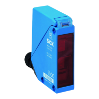
0
5
10
15
6%/90%
18%/90%
90%/90%
Distance in mm (inch)
mm
(inch)
100
(3.94)
200
(7.87)
300
(11.81)
400
(15.75)
500
(19.69)
600
(23.62)
700
(27.56)
1
2
3
Image H: WT18-3Xx3x /
-3Xx8x
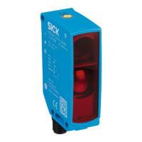
6%/90%
90%/90%
18%/90%
0
5
1
0
15
Distance in mm (inch)
mm
(inch)
100
(3.94)
200
(7.87)
300
(11.81)
400
(15.75)
500
(19.69)
600
(23.62)
700
(27.56)
1
2
3
Image:H-2: WT18-3Xx1x / -3Xx7x
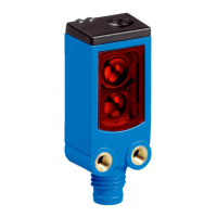
0
5
10
15
18%/90%
90%/90%
6%/90%
Distance in mm (inch)
mm
(inch)
200
(7.87)
400
(15.75)
600
(23.62)
800
(31.50)
1000
(39.37)
1
2
3
Image H-3: -WT18-3Xx2x
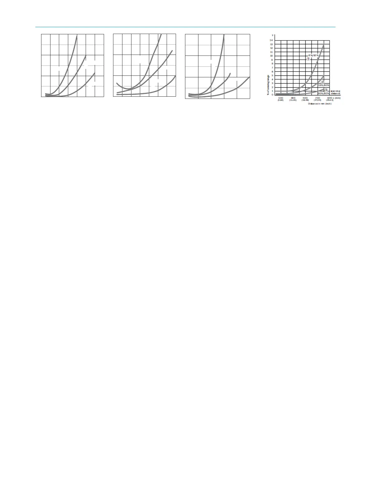
Image H-4: WTF18-3Vx1x
Technical data and connection diagrams (figure B) starting on page 69.