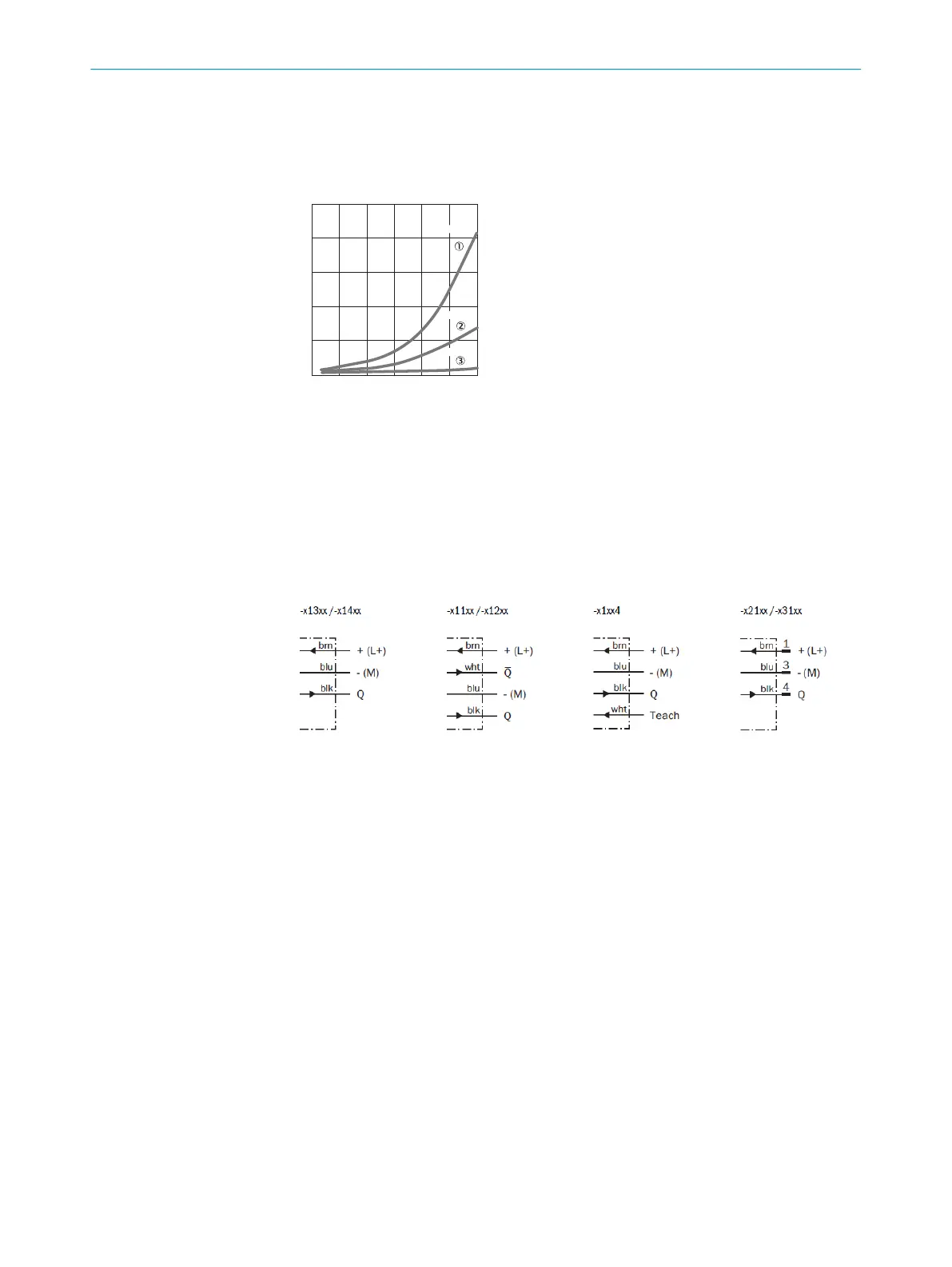
The minimum distance (= y) for background suppression can be determined from
diagram [H] as follows:
Exam
ple: x = 100 mm, y = 7 => 7 % of 100 mm = 7 mm. That is, the background is
suppressed at a distance of > 107mm from the sensor.
25
5
10
15
20
0
mm
(inch)
25
(0.98)
50
(1.97)
75
(2.95)
100
(3.94)
125
(4.92)
150
(5.91)
Distance in mm (inch)
% of sensing distance
6 %/90 %
18 %/90 %
90 %/90 %
Image: H
2 Mount the sensor using a suitable mounting bracket (see the SICK range of acces‐
sories).
Note t
he sensor's maximum permissible tightening torque of 0.8 Nm.
Note the preferred direction of the object relative to the sensor [see A].
3 The sensors must be connected in a voltage-free state (V
S
= 0 V). The inf
ormation
in the graphics [B] mus
t be observed, depending on the type of connection:
– Male connector connection: pin assignment
– Cable: core color
Image: B
Only apply voltage/switch on the power supply (V
S
> 0 V) once all electrical connec‐
tions have been completed. The green LED indicator lights up on the sensor.
Explanations of the connection diagram (Graphic B):
Switching outputs Q and /Q (according to Graphic B):
Teach-in = external teach-in (ET) (see Adjustment)
WTB4-3Exxxx and WTB4-3Fxxxx
D: dark-switching, output (Q) switches off when an object is present in the sensing
range.
WTB4-3P1362 and WTB4-3Px1xx
WTB4-3N1362 and WTB3Nx1xx
L: light switching, output (Q) switches when an object is present in the sensing ran‐
ge.
WTB4-3P1162 and WTB4-3N1162
WTB4-3Px262 and WTB4-3Nx262
ANT: complementary outputs Q and Q/
WTB4-3Pxxx4 and WTB4-3Nxxx4
L: light switching, output (Q) switches when an object is present in the sensing ran‐
ge. In addition: ET: teach-in function via cable.
Connect ET cable (PIN 2) to U
V
for > 2 s (PNP output)
Connect ET cable (PIN 2) to M for > 2 s (NPN output)
3 COMMISSIONING
2
8011166.126R | SICK
Subject to change without notice