AC MUM0096 rev. 07 - 27 -
MR21
18. BRAKE WITH DEGREE OF PROTECTION IP55
18.1. PRE-ADJUSTMENT OF THE BRAKE
The winches are normally supplied with the brake that must be
adjusted in accordance with the characteriscs of the system.
The braking distance depends on the compression of the brake's
springs; the springs need to be adjusted to obtain the braking
torque of the braking system that is suitable for the system, and
in compliance with
EN81.20-50 (See chart).
If addional adjustment is required, follow the instrucons re-
ported in the following chapter.
18.2. BRAKE ADJUSTMENT
The brake has two separate magnets so that the shoes operate
independently of each other.
Usually the brake shoes must open with the shortest stroke
possible, but without showing any fricon on the brake's drum
under the normal winch working condion.
Check periodically the status of wearing of the brake's shoes'
fricon material. In case of wear, proceed with the adjustment
operaons in compliance with what's provided in the following
chapters.
During each adjustment intervenon, make sure that between
the opened brake's shoe (winch free to rotate) there's a space
equal to 0.1-0.15 mm in the lining's lower part, by verifying with
a calibrated spacer.
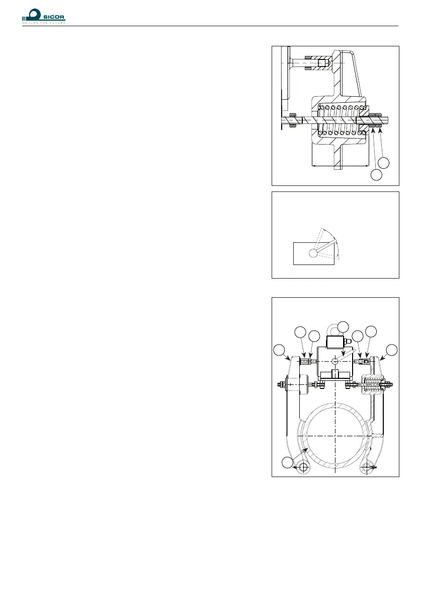
18.2.1. STROKE ADJUSTMENT
- Loosen the locknuts (2) on both the brake shoes and unscrew
the adjusng screw (1) leaving a clearance of 4-5 mm between
the screw and the brake shoe (5),
- turn the brake opening lever (6) to the “open” posion (POS2),
- ghten the adjusng screws (1) by hand unl they are ush
with the brake shoe (5),
- turn the brake opening lever (6) to the “closed” posion
(POS1) and ghten the adjusng screw (1) half a turn (equal
to about 10.1-0,15 mm in the lining's lower part) against the
brake shoe,
- ghten the locknuts (2).
18.2.2. CHECKING THE ADJUSTMENT
Move the cab up and down and listen to the noise level. The stroke is correct if the brake lining does
not touch the brake drum while the li is moving and if no noise is heard while braking. With the brake
opening lever in the “closed” posion, check the clearance between the brake shoe (5) and adjustment
screw (1), pressing on the electromagnet pin (minimum clearance = 0.5mm).
L min
3
4
1
2
6
1
2
5
5
7
BRAKE ON
(brake shoes closed)
POS 1
BRAKE OFF
(brake shoes open)
POS 2
BRAKE OFF
(brake shoes open)
POS 2