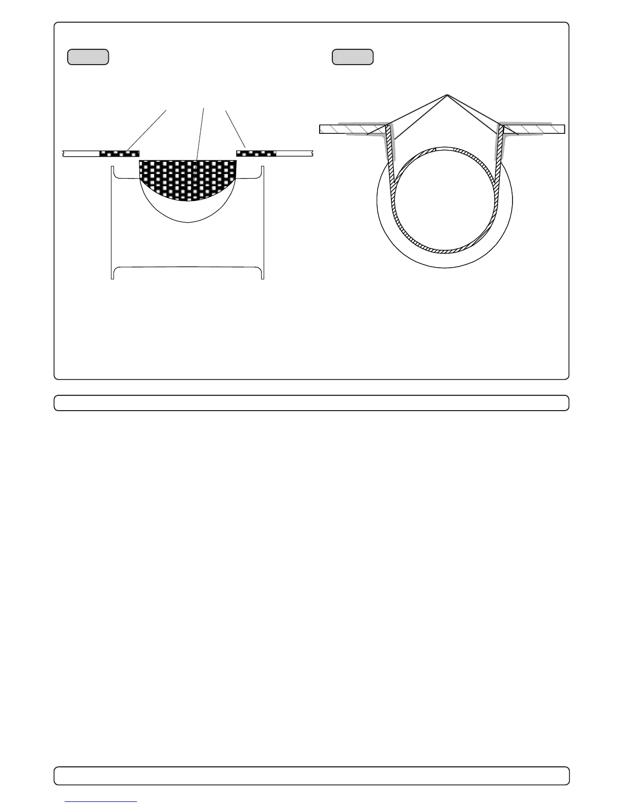
Grind off the bolt ange and
the gelcoat both inside and out-
side in the areas shown.
Fig. 1
Mould on installation of the stern tunnel
1. Make sure that there are enough space both inside and out-
side the transom of the boat.
2. Cut of the bolting ange on the stern-tunnel
3. Grind off the gelcoat both inside and outside the remaining
“tube” atleast 10 cm down on the “tube” (Fig. 1).
4. Offer the stern tunnel to the desired position on the transom
and mark around the tube.
5. Cut the marked hole in the transom of the boat.
6. Grind off the gelcoat on the transom of the boat in an area of
atleast 10 cm / 4” around the hole, both outside and inside
(Fig. 1).
7. Offer the stern tunnel to the transom in the desired horizontal
position, then bond to the transom with multi layers matt both
inside and outside (Fig. 2).
Take care not to reduce the internal diameter much, as this
will make it more difcult to mount the thruster
8. Apply gelcoat or similar on all bonded areas.
9. Install the gear leg on the stern-tunnel as described in the
installation manual for the thruster but t the oil feed pipe rst.
10. Basic installation of the motor assembly and electrical installa-
tion are described later in this manual.
Fig. 2
If a bow thruster is also installed, we advice to use seper-
ate battery banks for the two thrusters to avoid extreme
voltage drop if both thrusters were to be used at the same
time. Refer to the thruster manuals for adviced battery
capacity and cable sizes for each thruster.
Also ensure that you do not have direct connections of
both + and - if you have built together controls for both
thrusters to avoid current leakage between seperate bat-
tery banks.
If you are installing the standard Sidepower dual joystick
panel this is already secured.
Bond multiple layers both in-
side and outside
 Loading...