2.2.2 Connection Example B
This connection example shows the connection of the motion controller, if delivered
with external power supply unit and network cable.
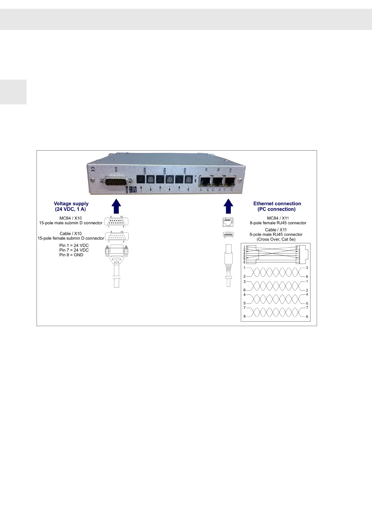
1. Mount a cable for the connection of the voltage supply to X10 according to the pin
assignment in the figure.
2. Connect the power supply cable with X10 of the motion controller and the adapter
to the mains socket.
3. Mount a cable for the connection of the PC according to the pin assignemt in the
figure (Cross Over, Cat 5e).
4. Connect the provided Ethernet cable with connector X11 of the motion controller
and with the network connection of the 2nd. network card of the PC or with the
LAN connector of the USB > Ethernet adapter.
Fig. 4: Connection of the Demo Kit hardware: connection example B
Installation and Setup
W
10 CNC 8x.00 - Demo Kit
2
 Loading...