Document No. 540-742
Installation Instructions
January 5, 2012
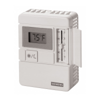
Table 2. LTEC Wiring Diagram.
Pin Wire
1 LONWORKS Net
2 LONWORKS Net
3 Power/ Service
4 Common
5 Setpoint/Ovrd
6 Room Temp
Twisted Pair
SASC0093R1
1
2
1
2
Pair 1
3
4
3
4
Pair 2
5
6
5
6
Pair 3
Table 3. TEC Wiring Diagram.
Pin Wire
1 Not Used
6 TX/RX
3 Room Temp/
Setpoint,
Override
4 Common
5 TX/RX
2 GND
Twisted Pair
SASC0126R1
1
6
1
6
Pair 1
3
4
3
4
Pair 2
5
2
5
2
Pair 3
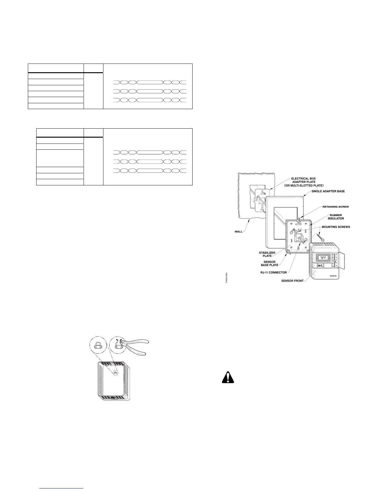
9. Plug the terminated cable into the RJ-11 port on the
back of the printed circuit board (PCB).
10. Feed the extra cable back through the hole in the
rubber insulator.
11. Snap the sensor front to the sensor base plate:
a. Hook the sensor front to the bottom latches.
b. Push the top of the sensor front into place until it
latches.
12. Tighten the sensor retaining screw with an Allen
wrench. See
Figure 3.
13. Connect the sensor to the RTS port on the TEC/LTEC.
The installation is now complete.
LTEC Temperature Scale Selection
LTEC sensors are factory-set for Fahrenheit temperature
scale. To display temperature in Celsius degrees, snip the
jumper (G) as shown in Figure 5.
SSEN0306R1
G
˚
F
˚
C
Figure 5. LTEC Room Sensor Jumper Location.
Electrical Box and Rough-in Mounting,
Typical
1. If a locator is attached to the rough-in device, remove
the locator by removing the two screws and lightly
rocking the locator to pull it free.
2. Untie the twist tie and pull about three inches (75 mm)
of the sensor cable into the space.
3. If you have a single-sensor electrical box, install the
electrical box adapter plate. See
Figure 6.
If you have a double-sensor electrical box,
install the required mounting plate(s).
If you use a universal adapter kit for a retrofit job,
install the multi-slotted plate in place of the electrical
box adapter plate. See Figure 6.
Figure 6. Electrical Box and Rough-in Mounting,
Typical.
4. Pull the cable from the wall, through the required
mounting hardware in the order shown.
5. Install the two sensor mounting screws provided but do
not tighten.
6. Mount the sensor base plate on the wall, noting the UP
arrow on the stabilizer plate:
a. Level the sensor base plate for appearance only.
b. Tighten the two mounting screws to the sensor
base plate.
CAUTION:
Over-tightening may cause the sensor base
plate to crack or bend.
7. Continue with Drywall Mounting (No Rough-in,
Typical), Steps 7 through 13.
The installation is now complete.
Siemens Industry, Inc. Page 3 of 4
 Loading...