Do you have a question about the Siemens MAMMOMAT 1000 Nova and is the answer not in the manual?
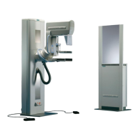
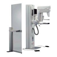
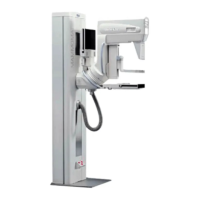
Overview of the Mammomat 1000 system.
Overview of the Mammomat 3000 Nova system installation.
Diagrams illustrating system configurations like radiation shield.
Identifies PC-boards and components on the stand.
Lists the PCBs, boards, and fuses used in the stand.
Details switches and other components on the stand.
Lists potentiometers, motors, and miscellaneous stand components.
Details signals and test points for the stand.
Details voltages and test points for the stand.
Shows cable connections in a block diagram format.
Details mains voltage connection and power supply for CPU.
Diagrams for lift and rotation mechanisms and drives.
Diagrams for compression measurement signals and motor drive.
Diagrams for Collimator 1 and Collimator 2.
Diagram for Automatic Exposure Control (AEC) system.
Information on connecting the generator to mains voltage.
Explains the functions of the control panel buttons and indicators.
Details signals and test points for the generator.
Visual representation of signal timing and sequences.
High-level block diagram of the system architecture.
Details grounding and power distribution across boards.
Shows how mains voltage is inputted into the system.
Master principle diagram of system operation.
Principle diagram for tube filament control.
Principle diagram for focus selection board.
Principle diagram for inverter control and kV regulation.
Principle diagram of the inverter operation.
Principle diagram for the control panel interface.
Principle diagram for the Automatic Exposure Control (AEC).
Shows physical connector locations on PC boards.
| X-ray Generator | High-frequency generator |
|---|---|
| Type | Mammography System |
| Manufacturer | Siemens |
| X-ray Tube | Molybdenum anode X-ray tube |
| Anode Material | Molybdenum/Rhodium |
| Target Material | Molybdenum/Rhodium |
| Focal Spot Size | 0.1 mm / 0.3 mm |
| Tube Voltage Range | 20-35 kV |
| Filter Material | Molybdenum/Rhodium |
| Compression Force | Adjustable, typically up to 200 N |
| Image Receptor | Film-screen cassette |
| Compression Paddle Types | Standard and magnification paddles |
| Magnification Factor | 1.5x |
| Biopsy Capability | Optional biopsy device attachment available |
| Image Storage | Film archiving |
| Power Requirements | 230V AC, 50/60 Hz |


 Loading...