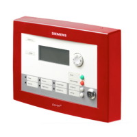
Differential Pressure Monitor Owner’s Manual
4-20 mA Signal Output Check
To check if the 4-20 mA Signal Output is functioning properly, follow these steps.
Equipment Required
•
•
•
•
•
•
Multimeter (digital or analog)
500 Ω Resistor
Portable Operator’s Terminal (POT) and cable.
Procedure
1. Connect the POT to the monitor’s communication port. If you are unable to establish
communication with the monitor, contact your local Siemens Building Technologies
representative.
2. Select the HW POINTS report from the Reports Menu.
3. Scroll so that the display shows LOOP SIGNAL (Point 49).
4. Set LOOP SIGNAL to 12 mA.
5. Turn the meter on and set it to monitor milliamps (mA).
Remove the wires from pins 13 & 14 and place one end of the resistor in pin 14.
6. Connect the meter to pins 4 and resistor (
Figure 9).
The meter should indicate a value of 12 mA (+/- .5 mA).
7. Set LOOP SIGNAL to 4 mA.
The meter should indicate a value of 4 mA (+/- .5 mA).
8. Set LOOP SIGNAL to 20 mA.
The meter should indicate a value of 20 mA (+/- .5 mA).
9. Release LOOP SIGNAL.
30 Siemens Building Technologies, Inc.
 Loading...