Connection
14 3ZX1012-0RB12-1AA1
English
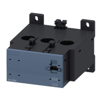
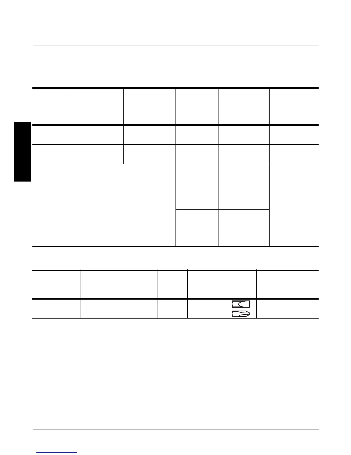
3.1.2 Current range 50 A to 820 A
Busbar connection: see graphics section, Fig. II
3.2 Auxiliary conductor connection
Thermistor
sensor
A link (A) is in place when the device is delivered. This
link must be removed when the sensor is connected
(see illustration in Fig. V and VI).
3.3 Connection scheme
See graphics section of Fig. IV for circuit diagram,
showing Automatic resets and remote resets.
Facility for connecting summation current transformer
3UL22 for external earth fault monitoring.
Finely stranded
conductor with
cable lug
[mm
2
]
Stranded con-
ductor with
cable lug
[mm
2
]
Connection
screws
Tightening
torque
[Nm/lb.in]
Tag
termination
[mm x mm]
3RB1253 35 to 95 50 to 120 M8 10 to 14 /
89 to 24
20 x 4
3RB1257 50 to 240 70 to 240 M10 14 to 24 /
124 to 210
30 x 6
3RB1262 50 to 240 185 to 240 M 10
(Connec-
tion to con-
tactor
3TF68)
14 to 24 /
124 to 210
40 x 8
M 12 (Con-
nection to
contactor
3TF69)
20 to 35 /
177 to 310
Solid
[mm
2
]
Finely stranded with/
without end sleeve
[mm
2
]
AWG Connecting screws
[mm]
Tightening torque
[Nm/lb.in]
1x(0.5 to 4)
2x(0.5 to 2.5)
1x(0.5 to 2.5)
2x(0.5 to 1.5)
20 to 14 0.8x4...5.5
Pozidriv 2
0.8 to 1.2/
7 to 11