Do you have a question about the Siemens 3RP25 and is the answer not in the manual?
Basic knowledge of low-voltage industrial controls is required to understand this manual.
Information on online support, product support, CAx data, applications, and documentation manager.
Details on DataMatrix code usage, its encoding, and its role with the SIEMENS Industry Support App.
Compliance with relevant EN, UL/CSA standards and shipbuilding approvals for the time relays.
Manufacturer's declaration of compliance with EC Directives and applied standards.
Explanation of the article number structure provided for informational purposes.
Notes on recycling, disposal, and protection against conductive contamination and electrostatic charge.
Specifies the allowed applications and proper use of the time relay hardware.
Important note for system safety and subscribing to relevant Siemens newsletters.
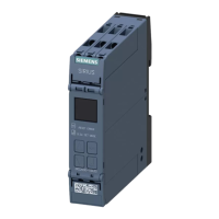
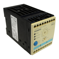
Diagram and labels identifying the main components of the time relay.
General description of electronic timing relays and their key benefits.
Details on available versions, sizes, and features of the 3RP25 time relays.
Information on operating temperature, time ranges, voltage range, and electrical service life.
Prerequisites and guidelines for correctly configuring the time relays.
Examples of functions and their typical applications in industrial systems.
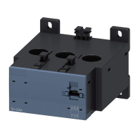
Diagram of components and accessories with their labels and article numbers.
Warning notices before installation, wiring, and commissioning regarding hazardous voltage.
Information on using coding pins to prevent errors when replacing terminals.
Procedure for mounting devices on a standard 35-mm mounting rail.
Procedure for removing devices from a mounting rail, including safety warnings.
Procedure and requirements for mounting devices on a level surface.
Procedure for disassembling devices from a level surface, including safety warnings.
Instructions for attaching and sealing the cover to prevent unauthorized access.
Procedure for labeling functions on multifunction relays using stickers.
Location and labeling of terminals on the device for proper wiring.
Diagrams showing terminal layouts for various 3RP25 device models.
Specifications for connecting terminals, including tools and wire sizes.
Procedure for connecting screw-type terminals, including safety warnings.
Procedure for disconnecting screw-type terminals, including safety warnings.
Guidelines for wiring spring-loaded terminals, conductor dimensions, and crimping.
Procedure for connecting spring-loaded terminals using push-in technology.
Procedure for disconnecting spring-loaded terminals, including safety warnings.
Procedure for plugging detachable terminals into the device.
Procedure for removing terminals from the device, including safety warnings.
Diagram showing the structure and labeled components of single function devices.
Procedure for setting the time range and operating time for single function units.
Details of the ON-delay function for specific 3RP25 relay models.
Details of the OFF-delay function for specific 3RP25 relay models.
Details of the asymmetrical flasher relay (clock generator) function.
Details of the star-delta function for specific 3RP25 relay models.
Details of the star-delta function with coasting time for 3RP2560.
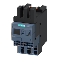
Diagram showing the structure and labeled components of multifunction units.
Procedure for setting time ranges and operating time for multifunction units.
Table detailing functions, output types, and circuit diagrams for multifunction relays.
Instructions to find technical data sheets via the Siemens Industry Online Support portal.
Drawings showing dimensions for 17.5 mm and 22.5 mm enclosure timing relays.
List of available accessories for 3RP25 time relays with designations and article numbers.
| Isolation voltage | 4 kV |
|---|---|
| Width | 22.5 mm |
| Number of contacts as change-over contact | 1 |
| Mounting type | DIN rail |
| Electrical life | 10^5 switching cycles at rated load |
| Operating temperature range | -25...+60 °C |