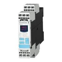
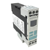
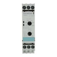
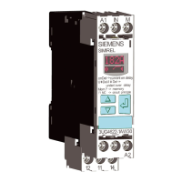
Do you have a question about the Siemens SIRIUS 3SK1 and is the answer not in the manual?
Defines user's role in ensuring product function within a system and liability.
Lists essential knowledge areas for comprehending the manual's content.
Specifies the manual's applicability and Siemens' right to update.
Defines the term '3SK1' as referring to all SIRIUS 3SK1 safety relay variants.
Explains the DataMatrix code on devices for information access.
Instructions for providing feedback and suggestions for manual improvements.
Covers general safety advice including recycling, disposal, and warnings.
Details the unsuitability of 3SK1 components for hazardous areas.
Defines the permitted applications and requirements for safe operation.
Highlights the need for special operational safety and product monitoring.
Manufacturer's declaration of compliance with EC Directives and standards.
Provides tables summarizing the different 3SK1 safety relay types.
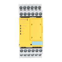
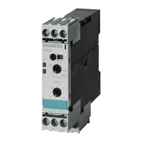
Illustrates and lists the various components and accessories for 3SK1 devices.
Details the functional capabilities and features of standard and advanced basic units.
Describes the primary use of 3SK1 safety relays in autonomous safety applications.
Explains typical system configurations for 3SK1 Standard and Advanced series.
Defines safety as a state where risk is reduced to a tolerable level.
Describes safety functions as reactions to events, involving detecting, evaluating, and reacting.
Explains fundamental terms like redundancy, single-channel, and two-channel.
General information, applications, and details for 3SK1 Standard basic units.
General information, applications, and features of 3SK1 Advanced devices.
Details on output expansions like 3SK1211 and 3SK1213 for system expansion.
Information on input expansions, specifically the 3SK1220.
Notes on configuring standard and advanced systems, including expansion rules.
Details the types of 3ZY12 connectors and their requirements for system expansion.
Defines rules for connecting expansions, power supplies, and termination connectors.
Provides internal circuit diagrams for standard, advanced, and expansion units.
Illustrates common wiring configurations for various sensor inputs and functions.
Crucial safety warnings regarding hazardous voltage before installation.
Explains the use of coding pins to prevent errors when replacing terminals.
Provides requirements and procedures for mounting devices on a flat surface.
Step-by-step guide for mounting 22.5/17.5 mm devices onto a standard rail.
Step-by-step guide for mounting 90 mm devices onto a standard mounting rail.
Procedure for safely removing devices from a standard mounting rail.
Procedure for mounting devices with connectors onto a standard mounting rail.
Procedure for removing devices with connectors from a standard mounting rail.
Procedure for mounting 90 mm devices with connectors onto a standard mounting rail.
Procedure for removing 90 mm devices with connectors from a standard mounting rail.
Procedure for mounting devices with connectors onto a wall surface.
Procedure for removing devices with connectors from a wall surface.
Procedure for mounting 90 mm devices with connectors onto a wall surface.
Procedure for removing 90 mm devices with connectors from a wall surface.
Instructions for attaching a sealable cover to secure DIP switches.
Details terminal assignments and connection data for narrower devices.
Details terminal assignments and procedures for 90 mm devices.
Guides on safely replacing defective devices with new ones.
Steps for setting configuration parameters like DIP switches and expansions.
Details the functions controlled by DIP switches for various parameters.
Describes the four main operating modes: Power-up, Configuration, Safety, Error.
Guidance on verifying safety-related output response times.
Step-by-step process for commissioning the 3SK1 safety relays.
Explains the meaning of LED indicators for different operating states.
Describes LED behavior during power-up and parameterization.
Lists common error statuses and their corresponding LED indications.
Provides diagnostic tables for configuration and safety modes.
Provides environmental, mechanical, and general specifications for 3SK1 devices.
Detailed specifications for 3SK1 Standard and Advanced basic units.
Specifications for output and input expansion modules.
Provides dimensional drawings for various 3SK1 device enclosures.
Shows dimensional drawings for different types of 3SK1 device connectors.
Form for reporting errors and suggesting improvements to the manual.
| Protection class | IP20 |
|---|---|
| Type | Safety relay |
| Series | SIRIUS |
| Function | Safety Relay |
| Response Time | < 20 ms |
| Mounting Type | DIN rail mounting |
| Width | 22.5 mm |
| Safety Integrity Level (SIL) | SILCL 3 |
| Performance Level (PL) | e |
| Category | 4 |
| Standards | IEC 62061, IEC 61508, EN ISO 13849-1 |
| Operating temperature range | +60 °C |
| Rated operational voltage | 24 V DC / 230 V AC |
| Operating Voltage | 24 V DC / 230 V AC |

