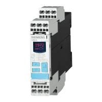
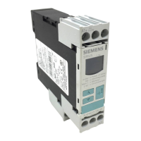
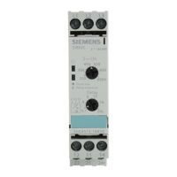
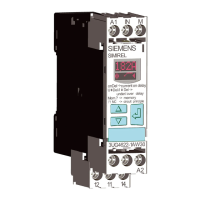
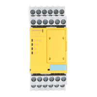
3SK1 devices
5.1 3SK1 standard
3SK1 safety relays
50 Manual, 04/2013, A5E02526190021A/RS-AA/01
5.1.4 3SK1112 Standard basic unit instantaneous (with solid-state outputs)
5.1.4.1 General information
MLFB:
3SK1112-*BB40 24 V DC
(*) 1: = screw-type terminal; 2: = push-in terminal
Device features:
● 4-way DIP switch for function setting (parameterization)
● SET/RESET button
● 4 LEDs for status and function display
● 2 sensor inputs (channels 1 and 2)
● 1 input (cascading circuit)
● 1 input (START pushbutton circuit)
● 1 input (feedback circuit)
● 2 test outputs
● 2 safe solid-state outputs
● 1 solid-state signaling circuit
● Enclosure width 22.5 mm
● Removable terminals
WARNING
In continuous operation for PL e / Cat. 4 in accordance with ISO 13849-1 or SILCL 3 in
accordance with IEC 62061, the key safety values apply in the case of a function test
interval (state change of the outputs) ≤ 1 year.
5.1.4.2 Function description
The 3SK1112 safety relay has two safety-related solid-state safe outputs and one non-
safety-related signaling circuit.
On the front of the device there is a 4-way DIP switch for function setting and 4 LEDs for
status and function display.
The SET/RESET button is used to load function settings and to restart the device (reset).
On commissioning, the device runs through a self-test. This checks that the internal
electronics and firmware are functioning correctly. All internal safety-critical parts of the
circuit are cyclically monitored for faults during operation.

 Loading...

